Thus, should an electrical component be reliable and safe, a knowledge of DC Hipot test set operation is important. These high-voltage test sets are indispensable in an industry where the integrity of insulation is always at stake. Therefore, their performance has to be measured to the last ounce with great precision while following all good practices. This manual is intended to explain the use of the DC Hipot test set and do this in a simple way, emphasizing safety and accuracy. If you have been in the trade or are relatively new to high-voltage testing, some concepts and methods will be presented here that will help you to achieve successful results in a way that will ensure that you work efficiently and remain safe. Read on to find out all that will maximize the use of your DC Hipot test set.
Understanding DC Hipot Testers

What Is a DC Hipot Tester?
The very Device High Potential Tester of insulation strength is used for everything related to testing electrical components, cables, or systems. The high DC voltage is applied to the test equipment, and the instrument seeks potential weakness in the equipment-under-test in the form of insulation breakdown or leakage current, which may cast doubt on safety or performance. Manufacturers use these types of testers for quality control, maintenance, and field testing, making sure that some safety and reliability criteria are met by the electrical system. The current generation of DC Hipot Testers possesses powerful features that enabled users to program different voltage levels, see digital displays for safe accurate measuring, and have built-in security features to ensure the safety of the operator against mishaps, as well as being protective of the equipment in case of an accident during testing.
Key Features of DC Hipot Testers
- Programmable Voltage Settings: Modern DC Hipot Testers allow users to enter a programmed voltage level, thereby dictating the entire testing procedure. This feature is particularly relevant when working with various productions and application testing.
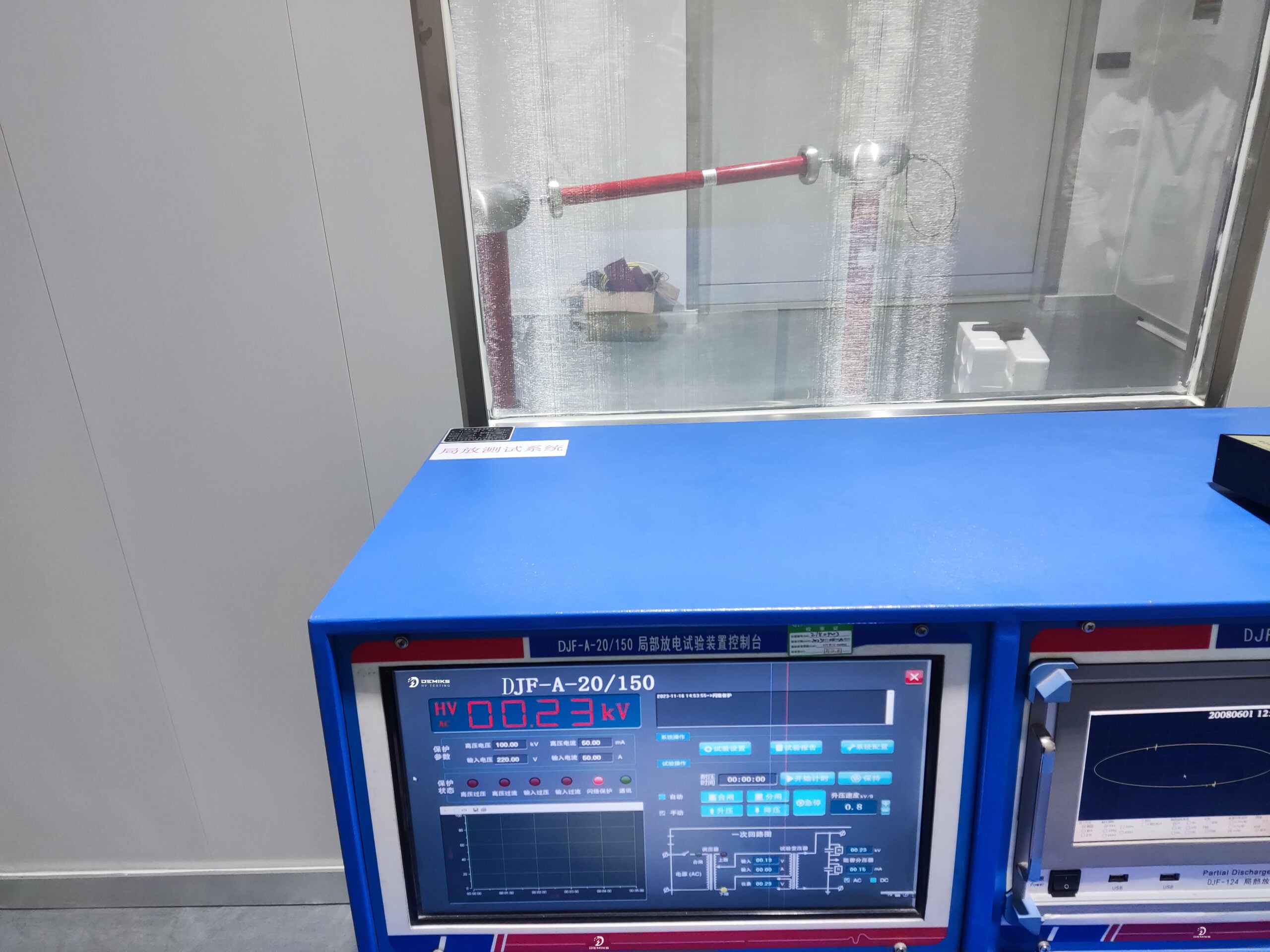
- Digital Measurement Displays: Since a tester provides real-time measurement data of voltage and current, it is used for precise and rapid analysis during the testing phase. This reduces the chances of errors in interpretation, thus giving immense convenience when using the instrument.
- Safety Features: In-built safety considerations, such as automatic cut-off, overcurrent protection, and mechanism discharge at high voltage, help ensure the safety of operators and devices, thereby averting inadvertent damage or injury during testing.
- Portability and Durability: Most test instruments are designed for transport, with ruggedness to match demanding environments. Thus, they prove equally amenable to field and on-site troubleshooting and laboratory work.
- Data Logging Capabilities: The most advanced models are capable of logging and retrieving data for detailed reporting or analysis. This is used where documentation is required or long-term monitoring is needed.
- Wide Testing Range: Typically, DC Hipot Testers cover a wide range of testing voltages and currents, accommodating applications from small-scale equipment to heavy industrial loads.
- User-Friendly Interfaces: The device’s intuitive controls and easy-to-use interface help reduce training times and increase test efficiency.
Incorporating these advanced features indeed ensures a dependable output from modern DC Hipot testers, ensuring safety and functionality standards for electric systems. Thus, they are invaluable tools due to their versatility and precision.
Common Uses of DC Hipot Testing
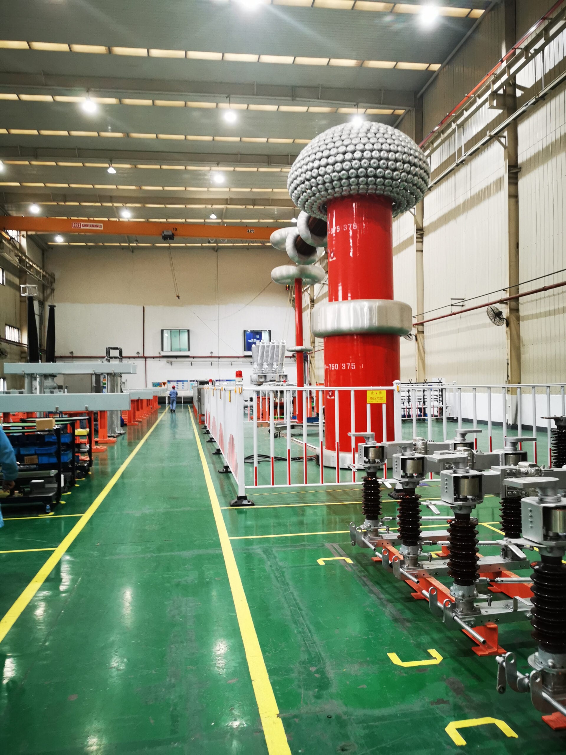
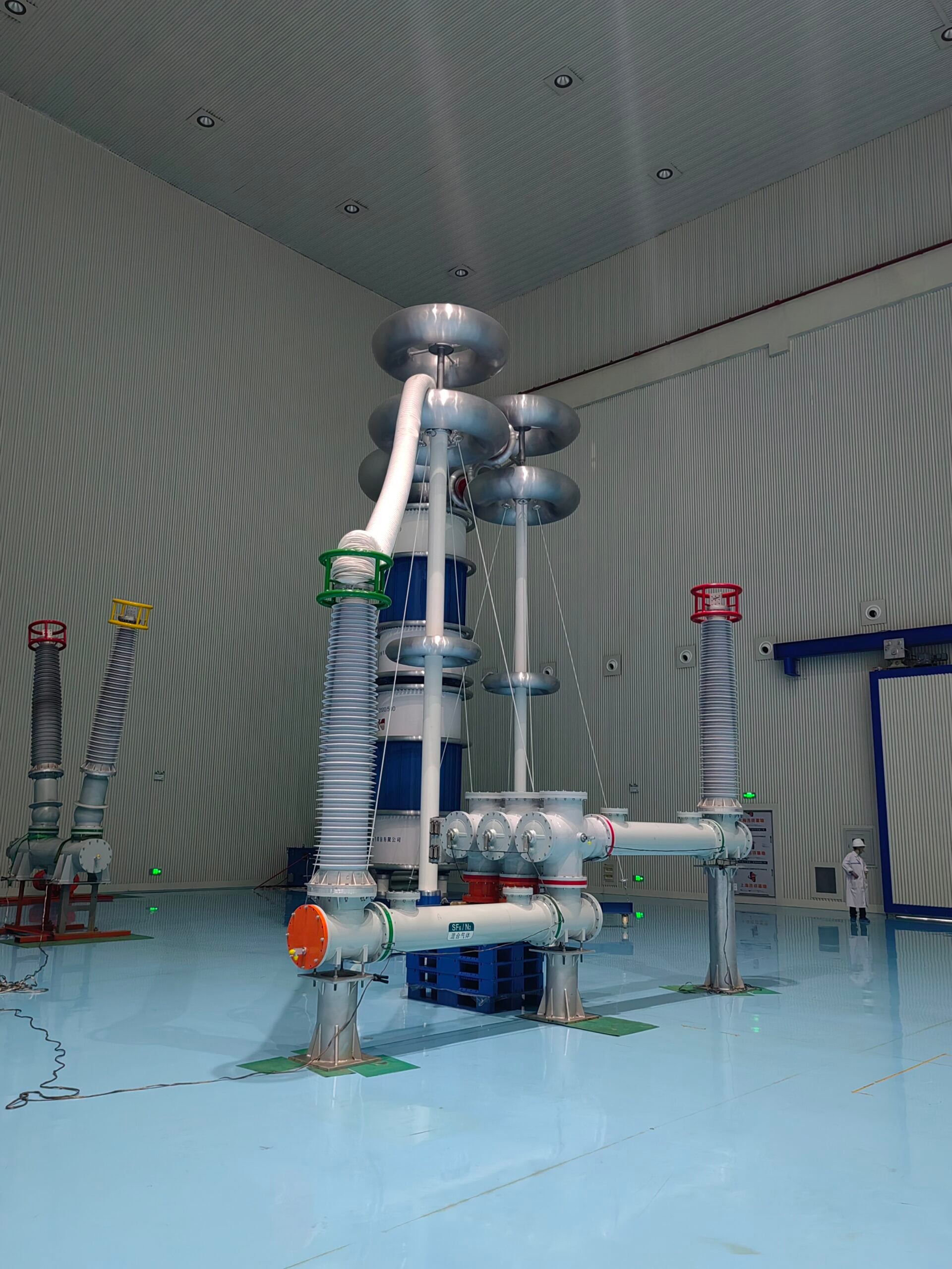
DC Hipot Testing is widely applied in various industries to ensure the safety and operational reliability of electrical systems. A major one is the manufacture of electrical equipment, where tests are performed on cables, transformers, and switchgear to ensure insulation integrity before deployment. The utilities also utilize DC Hipot Testers as part of an aging infrastructure assessment procedure, which helps identify potential faults in components such as circuit breakers and capacitors.
In renewable energy systems, such as solar and wind systems, DC Hipot Testing also ensures the ability of these systems to sustain operating stresses without degrading insulation. The aerospace industry also utilizes DC Hipot Testing, confirming that complex wiring systems maintain their performance under high-stress conditions and meet safety standards.
During design research and development, DC Hipot Testing is used to prototype and validate new electrical designs. The test reveals exact weaknesses in a system, enabling an engineer to correct any known issues before mass production. This level of assurance and flexibility accentuates the importance of DC Hipot Testing in electrical and electronic technology.
Components of a DC Hipot Test Set
High Voltage Output Specifications
The first connection to be considered in insulation testing is that of the test object to the high voltage generated by the DC Hipot Test Set for an accurate insulation test. The contemporary test set is capable of furnishing a predetermined adjustable high voltage in the range of a few hundred volts up to a few hundred kilovolts, depending on the application at hand. These systems are furnished with high-voltage operations of regulation to preclude any fluctuation during the test and to uphold a precise operation throughout the process. The more advanced ones even go as far as having digital displays of output voltage as well as output current, where this provides more fine-tuning adjustment and safety. The conventional high voltage output is also equipped with a ramp function that slowly steps up the voltage, thus minimizing stress on the test object. This further places the DC Hipot Test Set as an important industrial tool in determining the capacity and quality of an electrical system.
Safety Features in DC Hipot Test Sets
The DC Hipot Test Sets are all the safety features that can protect the user as well as the equipment during the performance of high-voltage testing. Some of the main safety characteristics include automatic discharge, whereby any slight electrical charge left in the system after testing is discharged to remove the hazard of shock or damage to the item under Test. Most of these units also provide protection against overvoltage or overcurrent conditions, which cut off all output as soon as such a situation occurs to avert impending danger. Such considerations to safety are additionally augmented through insulation monitoring and ground fault detection, whereby potential problems are detected promptly. Emergency stop buttons are provided for immediate halting of a test by the operator in case of any untoward incident during a test. These safety features complemented by interlocks and shields make the DC Hipot Test Sets a truly important set of instruments for providing a safe environment for testing.
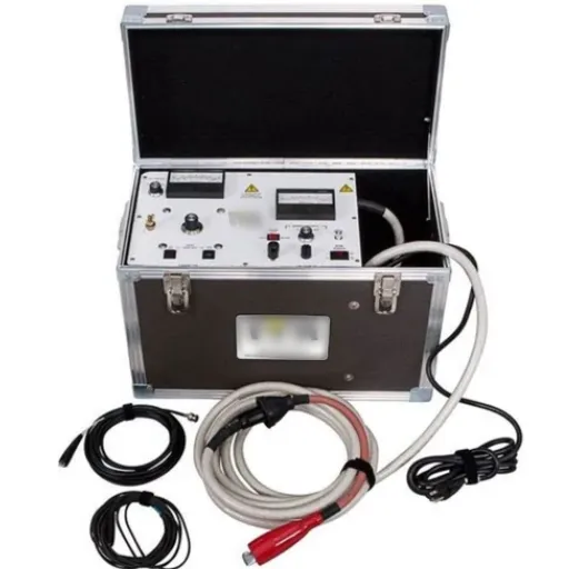
Model Overview: High Voltage PTS-200 or Otherwise
The PTS-200 went all and got an added edge in the large parking lot of industrial testing ever thought of-the huge portable DC Hipot Test Set able to undertake the full adventures of field and laboratory testing. This particular model is characterized by being compact and rugged, allowing it to give supreme high-performance tests. The PTS-200 has an interface that can be regarded as comparatively easy to operate for technicians and operators irrespective of how much experience they have, for its highest output voltage is 200 kV DC. Devices such as cables, switchgears, and transformers, which operate at high voltages, are tested using this instrument.
Other models in the product lineup include systems with voltage capacities ranging from 50 kV to 500 kV, to suit diverse testing requirements. Some of these models are equipped with digital meters to take readings, auto-test sequences for easy workflow, and other features; additionally, modernized safety features can be incorporated. Some station systems are modular, easy to transport, and quick to assemble on-site, making them valuable tools for all types of testing. These models offer the highest level of performance, reliability, and safety, meeting international testing standards and being of great importance to power industry personnel.
Operating a DC Hipot Tester

Preparation and Setup for Testing
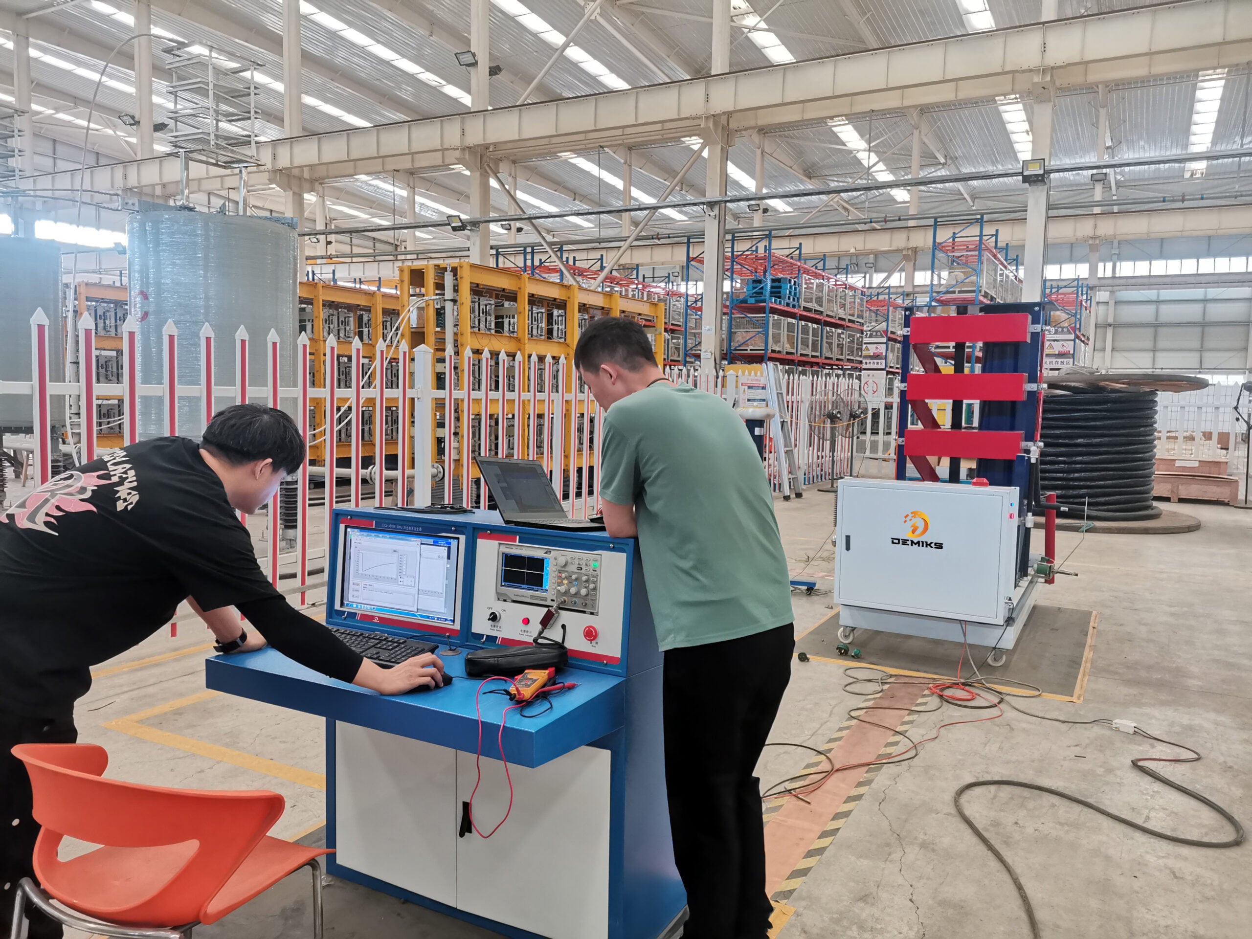
Before the test commences for the DC hipot tester, all the elements and the environment must be readied for a safe and accurate testing process. Suitable testing conditions, dry, well ventilated, and preferably free of any conductive material which would interfere with the test, must be prepared. Check for physical damage to the device and inspect all cables and connectors and other parts for any defects. Check whether the tester has been calibrated and whether it is operating within the tolerance stated by the manufacturer.
First, make arrangements to facilitate this device or system under test by the usual method of disconnection-from power and isolation-from other equipment. Ensure that all safety precautions are set up for personnel, such as the use of personal protective equipment and the erection of barriers against potential hazards. One must consider good earthing of the test equipment. The ground lead of the tester should be connected to the ground of the object under test whenever possible to cancel out any undesired discharge. Also, ensure that the test parametric ranges of voltage and current are well within the limits allowed by the particular procedure or standard. Once the above points have been met, one may start the testing.
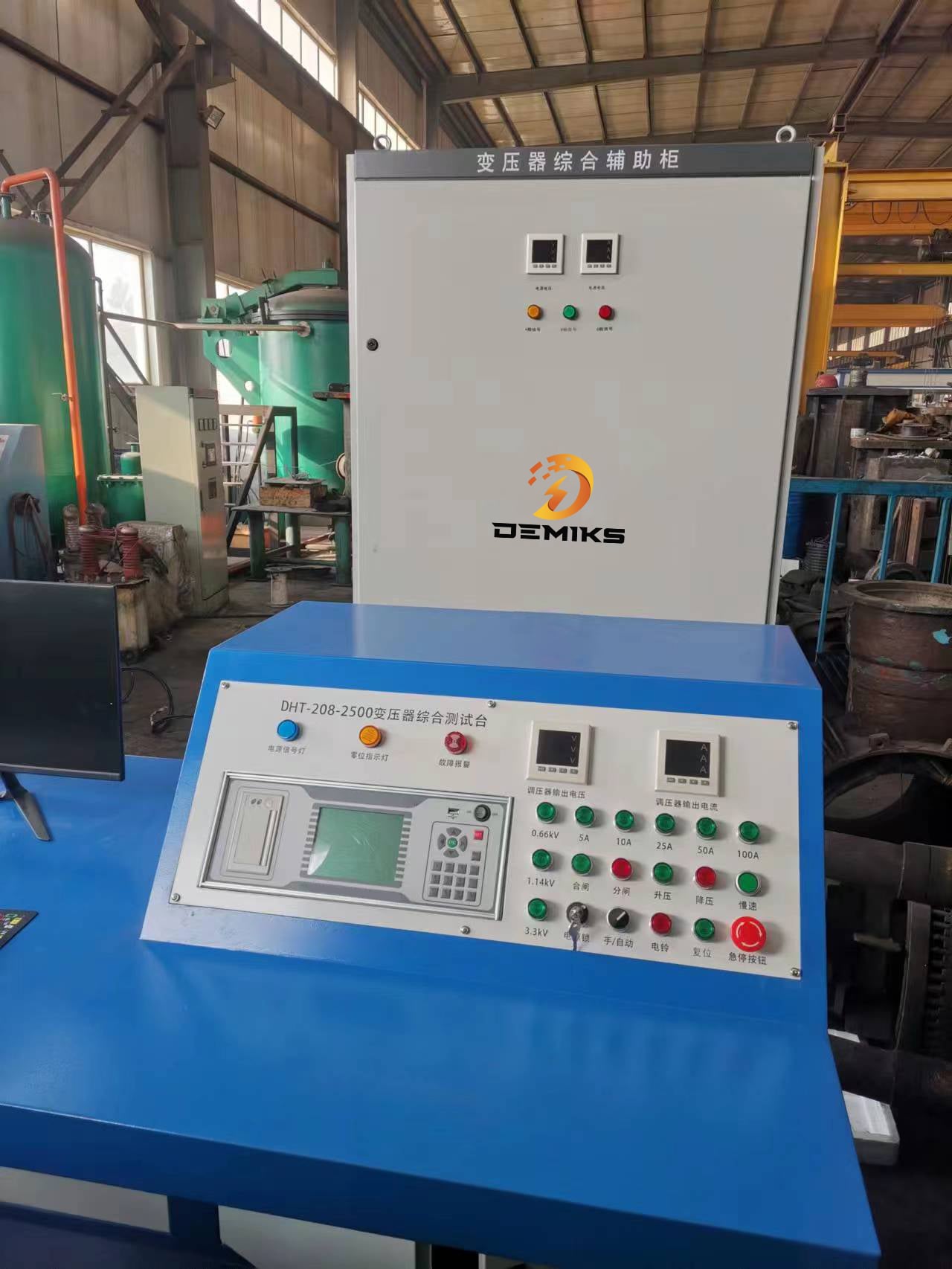
Understanding Test Parameters: KV and MA Ratings
In general, kV and mA ratings become very crucial in performing electrical tests for accurate measurements and safety. The kV rating is the level of voltage applied to a test and is important in testing the dielectric strength or insulating ability of the test object. With higher kV ratings, one conducts insulation tests for comparatively stronger insulation, like power transformers or high-voltage overhead power lines.
mA rating, on the other hand, refers to the amount of current flow during the test. It is of critical importance to observe the mA since a higher-than-expected mA reading may indicate a failure in the insulation or an unintended leakage path through the test object. For instance, if the insulation under test yields a higher mA value, that will indicate that the insulation is failing or is not suitable for the type of working conditions it must face.
Precise calibration and monitoring of these parameters guarantee that the testing conditions conform to industry standards and mitigate potential risks. Through prudent setting of kV and mA parameters, technicians can improve the reliability of electrical systems; likewise, they ensure that test equipment and personnel are safe during the testing operation.
The Test: A Step-by-Step Process
- Preparation and Safety Check: Ensure all safety procedures are followed. Inspect the test equipment for any visible signs of damage or wear. Confirm that the testing environment is free from unnecessary personnel or obstructions. The equipment should be correctly insulated and grounded, and all involved should wear PPE.
- Set up the Equipment: Connect the testing device to the equipment or components being tested. Double-check all connections to ensure they are secure and properly configured. Input the required parameters, such as voltage (kV) and current (mA), according to the specific test requirements and industry standards.
- Pre-Test Calibration: Calibrate the testing device to ensure it reads correctly. With calibrators, verify that the setup aligns with the designated parameters. This will prevent any drift that could compromise the test result or safety.
- Perform the Test: Slowly raise the voltage/current to the required levels. Scrutinize the actual readings from the testing device for any abnormal behavior or fluctuation. Communication with the whole group of members should be sustained so that all observations can be recorded in real-time.
- Documenting Results: Measurements and observations must be thoroughly documented to maintain a comprehensive record of the test. Any anomalies or deviations from the expected result should be reported along with any environmental factors that may have affected the test. This information would be considered very useful for analysis and future reference.
- Post-Test Inspection and Shutdown System: After completing the test, carefully de-energize and disconnect the testing equipment. Inspect the tested components and testing device before and after testing to ensure no damage was incurred during the process. Store all equipment properly to protect it for future use.
- Analysis and Reporting: Analyze the test data to identify trends, weaknesses, or failures in the equipment. Prepare a complete report detailing the procedure, results, and any recommendations about further improving system performance or for the immediate correction of any such issues. Place the report in the hands of all stakeholders as soon as possible, so they can begin their review and take any necessary action.
Interpreting Test Results

Dielectric Strength Measurements: An Overview
Dielectric strength tests are applied for verification of the insulation properties of materials destined for utilization in an electrical system. The parameter specifies the maximum value of an electric field that a material can sustain without suffering breakdown or loss of its insulating properties. Conditions come into play affecting these measurements-these encompass the material’s compositions, surface conditions, and thickness, as well as external factors such as temperature and humidity.
Modern methods involve the utilization of specialized instruments to ensure accuracy and reproducibility while determining dielectric strength. For instance, high voltage testers and special electrodes are employed in the application of electric fields of precisely controlled intensity across the specimens under test. They show data about the breakdown voltage and the breakdown field intensity, thus proving highly useful in the comprehension of the reliability of materials and their safety under operating stress.
Based on the interpretation of these measurements, an engineer predicts performance, prevents failures, and, consequently, complies with stringent safety standards. When it comes to testing dielectric strength, the scope of its application spans various industries, including power generation, automotive, and aerospace, emphasizing that designing robust and reliable electrical systems would be impossible without it.
Analyzing Insulation Resistance Data
In-course analysis for insulation failure helps the safety and dependability of an electrical system. Being a resistance measurement in insulating material, it determines how an insulating material deteriorates or gets contaminated or defective against deterioration in performance with time. The data of insulation resistance would be accurate enough for the assessment of the equipment condition and assuring the concept of predictive maintenance against imminent failure.
Due to advancements in testing technologies, data collection and monitoring have become increasingly precise, enabling more informed decision-making regarding the life-cycle assessment of an electrical component. These capabilities enable engineers not only to view trends over time, ensuring the design complies with industry standards, but also to facilitate stronger system design.
Set Pass/Fail Criteria
Pass/fail criteria must be established, as this is a crucial aspect that ensures reliability and guarantees cohesiveness in testing electrical components. These criteria are usually determined based on industry standards, manufacturer specifications, and operational specifications of the system in question. With the state-of-the-art data analytics and real-time monitoring capabilities, an engineer can determine the component’s performance based on a set of predefined threshold values, such as insulation resistance, thermal tolerance, or electrical conductivity.
Of course, such trend analysis can aid in spotting potential problems that might blossom into failures down the road. For example, the onset of a stretching curve in insulation resistance may indicate aging or wear; in such cases, maintenance can be scheduled beforehand. Clearly, establishing proper criteria and maintaining them over time would allow for ensuring the quality and safety of components, ultimately supporting the best performance of the system.
Safety Considerations in High Voltage Testing
Electrical Safety Protocols
This would be my first consideration when talking about electrical safety protocols and high-voltage testing: human, equipment, and environmental safety. My first consideration for the safety matters would be the commonly accepted safety standards: OSH and NFPA 70E. Then, essential personal protection equipment (PPE) should be considered: insulated gloves, face shields, arc-rated clothing, and safety boots. An LOTO procedure should occur 100% of the time to ensure the equipment remains de-energized during testing/servicing to prevent accidental energization.
This would be my first consideration when talking about electrical safety protocols and high-voltage testing: human, equipment, and environmental safety. My first consideration for the safety matters would be the commonly accepted safety standards: OSH and NFPA 70E. Then, essential personal protection equipment (PPE) should be considered: insulated gloves, face shields, arc-rated clothing, and safety boots. An LOTO procedure should occur 100% of the time to ensure the equipment remains de-energized during testing/servicing to prevent accidental energization.
Several key considerations must be evaluated during another risk assessment before carrying out any high-voltage testing. I usually identify hazards, contemplate the probability of the hazards, and then consider mitigating them in their risk assessment. Training is significantly impactful on the safety of the involved parties in the sense that they should be aware of electrical hazards, emergency responses, and procedures pertaining to the equipment under test. I think that striking a balance between the approach to risk reduction and strict enforcement of safety standards allows to develop a safe and controlled environment during high-voltage testing.
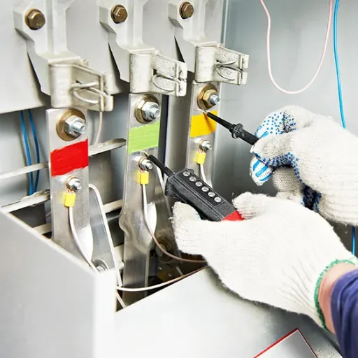
Ground Bond Testing and Continuity
Ground bond testing and continuity verification are conducted mainly to ensure safety and reliability of an electrical system. Basically, ground bond testing subjects the grounding connections to a level of fault current, which is low in magnitude, measures the resistance developed between the grounding pin of the device and safety ground. This resistance must be such that it shall permit the harmless flow of excessive current during fault into the earth so as to shock-protect any user and to prevent any further damage against any equipment. I use an instrument to make a precise measurement of resistance values under some approved standard requirements, be they UL, IEC, or ANSI.
The main task of continuity testing is to ensure the integrity of the electric circuit paths. This means ensuring that no breaks exist in the connections and that all currents flow freely in the direction intended. I use cutting-edge test equipment to measure low resistance values, connecting to a strong link, and look for any weak points or faults in the wiring system. By performing these tests step by step, I ensure that all components serve their purpose and provide maximum safety to end-users.
In-house testing of devices became my standard early in my career, with respect to thorough grounding and continuity tests, as well as regular maintenance, so I can proceed to check and eliminate potential access points. I stay informed about industry advances and developments in testing strategies to employ the best possible practices and take a balanced perspective on security and performance issues. The focus that I bring about is the reliability of equipment in terms of user safety in line with the most demanding standards applied in high-stakes electrical applications.
Common Hazards and Precautions
Electricity is always present in dangerous situations that require measures to avert accidents. The most terrible hazard is electric shock. It happens when a man’s body comes into contact with either a live wire or an insufficiently insulated piece of equipment. For my protection, I put on insulating gloves and rubber-soled boots and all necessary PPE at the job site. The lockout/tagout procedure is strictly followed by me so that when work begins, electrical energy is isolated. Before proceeding with their preventive maintenance against shocks, regular checks of their tools and equipment must be undertaken to identify any damage, such as frayed cables or worn insulation.
Another Danger involves arc flash and burns-the sudden release of energy caused by an electrical fault or short circuit. Having no adequate measures in place, a scenario can lead to life-threatening injuries. Thus, with regard to work on energized systems on-site, I take into consideration the latest arc flash boundary data, as well as comply with the set standards, such as NFPA 70E. Arc-rated clothing, shields, and facial protection must be worn after performing a risk assessment before the work is carried out.
Wires must be fastened when going anywhere, especially when they serve as tripping hazards. I always ensure that cables are neat and tidy and get suitable cable organizers, keeping all walkways clear of wires. Most essential to me is staying abreast of all current safety codes and electrical systems, mathematically achieving the most applicable safety precautions for implementation. Schedules of repeated training and ensuring time is put aside to install safety measures guarantee the chose safety and efficiency in all my undertakings.
Reference Sources
- PTS-series-digital-Manual-2k18.pdf – A detailed operator manual for high voltage test sets, including features and safe operation guidelines.
- HZZGF-DC-Hipot-Tester-User-Manual – Provides instructions for operating and maintaining a DC Hipot tester to ensure longevity and safety.
- Manual Hipot Tester Operation Manual – Offers step-by-step guidance on using a manual Hipot tester, including voltage adjustments and safety precautions.
- Phenix Technologies Inc. DC DIELECTRIC TEST SET – Highlights the importance of safety procedures and proper operation of high voltage test equipment.
- Whitepapers – Exploring the Necessity of the Hot Hipot Test – Discusses the role of Hipot testing in verifying insulation strength and ensuring electrical safety.
Frequently Asked Questions (FAQs)
❓ What are DC hipot testers, and what are their applications?
Imagine for a moment that anyone truly wanted a tool or machine’s accident arising just because of wires spread on the floor. Being a tripping hazard is the last thing those who take their safety seriously want these wires to be. I try to keep cables neat and orderly; I do get the appropriate cable organizing paraphernalia, and I keep the walkways clear as much as possible. I foresee that I stay updated with all the newest safety codes and electrical systems; with this, I am able to uphold the highest level of safety measures. Regular training and thorough planning on the implementation of safety measures stand to ensure that all the projects under my command are safe and well executed.
❓ How does a DC hipot test work?
The application of high voltage into the insulation of electrical components while leakage current is recorded by such a DC hipot test. Normally, the DC hipot tester would ramp the voltage from zero to a particular level, say 0-200 kVDC. An insulation resistance tester is installed in the device to verify that the insulation under test can withstand a high potential applied across it without breakage. Leakage current above the stipulated limit means the possibility of defective insulation. These tests have to be carried out to fortify the reliability and safety of electrical systems, mostly if carried out on a production line.
❓ What are the differences between AC and DC hipot testing?
The significant difference between AC and DC hipot tests is the kind of voltage applied during the test. AC hipot testing, or the application of an alternating current, involves detecting insulation failure under conditions that differ from those detected by a DC test. In contrast, a DC hipot test set applies a direct current that is generally more suited for testing the insulation resistance of capacitive loads. Each method has specific merits; typically, AC hipot testing is used for equipment operating on AC power, while DC testing is used for applications operating on DC. Both are essential in the field of electrical safety testing.
❓ What is the standardized output current of a DC hipot test set?
Depending on the make and use application, a number of standard output currents are common for DC hipot testers. Set at 5mA, 10mA, and 20mA, these testers offer flexibility in testing electrical apparatus. For instance, the 4100-10 model of Phenix Technologies is suitable for tests needing a 10 mA output. Selecting the appropriate output current is a necessity for having testing done correctly without damage to the insulation being tested. The insulation resistance in the object under test must also be taken into consideration since it will define the current that will flow through during a test.
❓ What features should a portable DC hipot tester have?
When considering a portable DC hipot tester, there are various features that may take priority in purchasing decisions. Primarily, have yourself an adequately large voltage range of up to 200 kVDC, to be able to test a wide range of materials. Intuitive operations and programming stand as another plus. Safety features must be present, such as ground bond test capability, to ensure that safety is being looked after during testing. For portability, one must look for a lean and compact design that allows tool carrying around on the production line. Ikonix and JM Test Systems, normally found, present exemplary choices for portable models.
❓ How often should calibration be carried out for a DC hipot test set?
Before measuring anything, one must consider every slight factor that might interfere with the precision of the measurements. Therefore, the DC hipot test set must be regularly calibrated to achieve meaningful and conclusive test results. Calibration frequency depends on the manufacturer’s recommendations and is recommended to be performed at least once a year. If equipment is subjected to frequent use or operates in harsh environments, it will require more frequent calibration. The output voltage and current measurements should be set forth correctly to ensure that testing is correct and not due to an error in a side measurement. Another good practice is to keep a record of these calibration dates to ensure compliance with safety test standards.