High-voltage circuit breakers are paramount components of an electrical power system, acting as the initial means of resistance against faults and hence maintaining stability and safety within the power distribution network. Being very intricate in their design, they certainly develop faults with time. Testing and maintenance serve to prevent a breaking down of these accessories, thus improving reliability and operational efficiency. This article aims to provide a summarized account of general methods and best practices involved in HV circuit breaker testing so as to provide readers, which includes engineers, technicians, and practitioners, with a well-rounded understanding. One is set to learn a great deal that would enable him to keep such assets fully operational, ranging from diagnostic testing to more advanced test procedures.
Understanding High Voltage Circuit Breakers
What Are High Voltage Circuit Breakers?
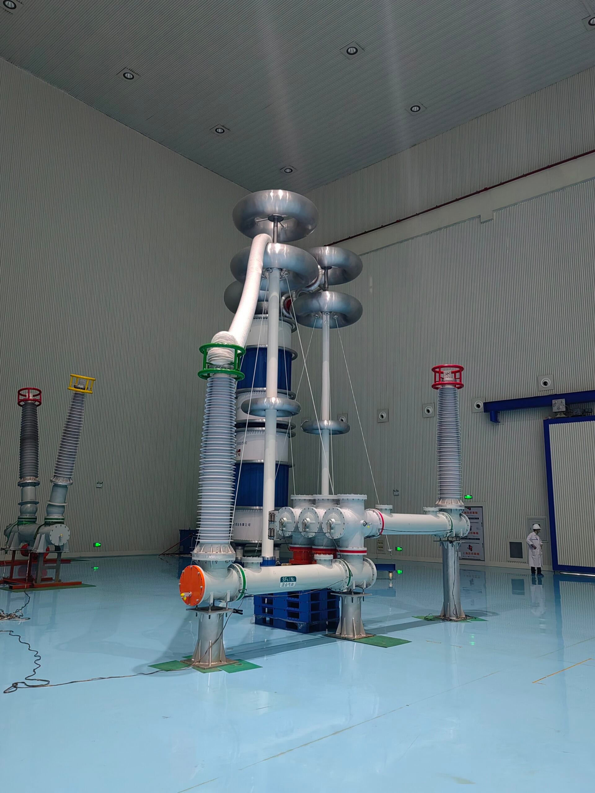
Being among the very few high-end electrical equipment, Circuit breaker (also known as a breaker in the short term) installation is always of the highest priority in all power systems. They interface and control electricity flows in high-voltage networks. Nominally, a high voltage refers to a voltage value above 36 kV for a breaker; it is an autonomous safety system designed to break fault currents and prevent damage to the equipment and outages to the power supply. The primary role is to isolate fault conditions quickly, in milliseconds, thereby helping to maintain system stability and minimizing danger.
Switching mechanisms of CO2 circuit breakers found the arc extinguished in SF6 gas: to be specific with vacuum and jet-oil respectively. SF6 circuit breakers are the best owing to Sulfur Hexafluoride gas being a great super insulator and quenching the arc very fast. Vacuum circuit breakers, though, require nearly no maintenance and are environmentally friendly. With the advent of modern technologies came digital systems for supervising the HV breakers and delivering real-time diagnostics and predictive maintenance approaches.
The testing proce-dure to ascertain the safety and performance standards for HV circuit breakers is conventionally dictated by industry standards such as the IEC and IEEE. The tests help evaluate parameters considered critical for successful operation and reliability in power distribution systems, such as dielectric strength, contact resistance, and operating timings. Being combined in their operation, HV circuit breakers are principal actors in protection schemes for massive power grids, industrial powerhouses, and infrastructures.
Importance of Circuit Breakers in Power Systems
Circuit breakers have served as the very foundation of contemporary power system operation and design, providing continuous electrical service to consumers while protecting equipment and personnel. With the increasing complexity of the grid and the integration of renewable energy sources, circuit breakers have evolved in sophistication and are now equipped with advanced protection and automation functionalities, in addition to conventional fault isolation. Modern intelligent circuit breakers, equipped with microprocessor-based relays, are capable of monitoring load currents, analyzing fault patterns, and communicating with supervisory control systems to optimize network performance.
Key Impact Statistics
According to statistics, faults in power grids, such as short circuits and overloads, lead to numerous hours of downtime and millions of lost productivity annually. Faults are detected and interrupted by circuit breakers in milliseconds, preventing them from causing a catastrophic disruption in the system or any other type of damage.
With the advent of new materials, the engineering of high-voltage circuit breakers has improved in terms of efficiency and environmental sustainability, utilizing alternative materials such as SF₆-free alternatives or vacuum technology. These devices have been developed to handle voltages as high as 800kV in some cases, thereby allowing a sturdy infrastructure to support megacity grids, interconnected networks, and decentralized generation systems.
It is through this evolution that foregrounds breakthroughs in deciding resistance, efficiency, and interface on smart grid development, depicting the indisputably potent edge in global energy reliability and sustainability.
Common Types of High-Voltage Circuit Breakers
High-voltage circuit breakers differ in terms of the primary interrupting medium used, which influences their respective performance, reliability, and suitability for a specific application. Some of the very prevalent types in present-day power systems include:
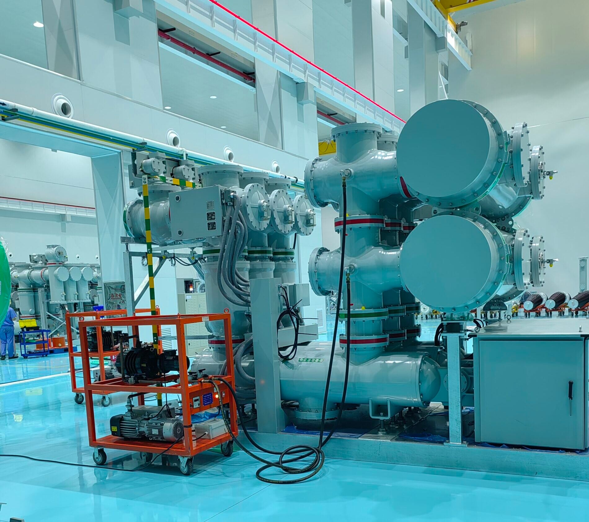
SF₆ Circuit Breakers
Due to fine arc-quenching properties and high dielectric strength, SF₆ circuit breakers have become one of the most commonly used breakers for all levels. It efficiently interrupts at voltage levels up to 800kV and above. Compared to any free-air system, SF₆ gas uses.
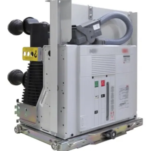
Vacuum Circuit Breakers (VCBs)
They use vacuum interruption, in which a very high vacuum interrupts the arc by essentially removing ionized particles. Being more capable in medium to high voltage, their use is mainly in the industrial and utility sectors. Other advantages include low maintenance, longer lifespan, and improved performance in areas with frequent operations. They are also safer from an environmental point of view because, unlike SF6, gases are not used in VCBs.
Air-Insulated Circuit Breakers
They interrupt the arc using air and rely primarily on a high-speed mechanical operation for arc extinction. Typically, low-to-medium voltage applications tend to use them, though they are increasingly used for the higher voltage systems. AICBs are indeed suitable for being cheap and straightforward, but are larger in size because air has a low dielectric strength.
Oil Circuit Breakers
Oil circuit breakers were formerly considered the standard in high-voltage operation. In these breakers, oil was used both for insulation and for extinguishing the electric arc. During an operation, the oil extinguished the arc by cooling it and absorbing its energy. With the improvement of SF₆ and vacuum technology in the industry, their use has dwindled, though they continue to find acceptance for incorporation into older generation systems or for products in rural locales.
Hybrid Circuit Breakers
Since the features of more than one technology are combined, hybrid circuit breakers most commonly combine gas-insulated and vacuum technologies to maximize performance and minimize their carbon footprint. These solutions are gaining traction for use in the smart grid and renewables integration landscape, where precision in operation and a low carbon footprint go hand in hand.
High-voltage circuit breakers of each type have their own unique features and advantages for specific applications. The selection criteria depend on voltage levels, weather conditions, and maintenance cost-effectiveness, among other factors, so that the technology meets the operational purposes.
Testing Solutions for High Voltage Circuit Breakers
Overview of Circuit Breaker Testing Methods
There are several tests for high-voltage circuit breakers, which checks for the breaker`s dependability, operational safety, and conformity to industrial standards. Performance may be evaluated according to one of various methods, detection of faults, using specifications found in operating manuals, or by setting up particular conditions worthy of consideration. Such testing is basically put in mechanical, contact resistance, insulation, and dynamic tests.
Mechanical Testing
Mechanical testing evaluates various parameters related to the operating mechanism, focusing on breaker opening time, closing time, stroke length, and contact velocity. Modern time-motion analysis software is utilized to ensure precision in determining deviations from the defined performance threshold. Balanced mechanical operation performance reduces the chances of failure during essential fault-clearing operations.
Contact Resistance Testing
Through this procedure, the contact resistance of both Main and Arcing contacts is measured to assess any possible wear, rusting, or formation of loose junctions. It is essential to maintain low and uniform contact resistance to minimize energy losses and heat generation in high-current flow conditions.
Insulation Tests
The insulation test checks the condition of the breaker’s insulating materials by subjecting them to high-voltage DC or AC signals. The insulation resistance test ensures that no leakage current diminishes performance, while the dielectric strength test measures the highest voltage the insulation can withstand before breaking down.
Dynamic Testing
Dynamic testing provides detailed analysis of breaker switching, including synchronized pole operation, contact travel curves, and operating speeds. Timing analysis is performed to ensure the breaker operates within acceptable limits, thereby ensuring stable system operation and preventing cascading failures during fault occurrences.
Operators use these testing techniques to ensure the performance of high-voltage circuit breakers and extend their lifespan. By installing these diagnostic tools and monitoring systems, potential failures can be detected before they become large, reducing downtime and maintenance costs, thereby enhancing the reliability of the power grid.
Voltage Tests: Ensuring Electrical Integrity
As crucial checks for electrical insulation and the operation of machinery under high voltages, voltage tests ensure that the insulating materials and all circuit components can withstand the electrical stresses that may be applied to them during service. The main types of voltage tests conducted in high-voltage systems are dielectric withstand tests, partial discharge tests, and impulse voltage tests.
Modern Testing Enhancement
With the integration of advanced monitoring technologies, such as digital sensors and real-time data analysis in voltage tests, the accuracy and reliability of testing have been significantly enhanced. An end-to-end testing procedure following rigid specifications ensures uniformity of results, which in turn are imposed by industry standards, such as IEC 60060 and IEEE Std 4.
Early detection of insulation faults through regular voltage tests acts as a catalyst for extending the life of equipment and protecting it from total failure in high-voltage systems.
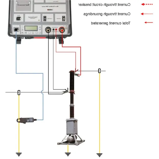
Contact Resistance Tests and their Importance
Contact resistance tests serve as a vital diagnostic tool to assess the integrity and performance of electrical connections, which essentially include circuit breakers, disconnect switches, and busbar joints. An increased resistance could be caused by contamination, oxidation, or even wear; in other words, any resistance due to substances at the contact interface is detrimental to operation as it causes energy losses or overheating.
Industry Guidelines
Industry guidelines dictate that contact resistance values should be within certain limits, typically in the range of micro-ohms. Any increase might indicate degraded connections that could fail, depending on the extent of deterioration, if not addressed.
With modern measurement instruments, the technique is tested with high precision, utilizing DC currents of approximately 50 to 200 amperes to break down surface contaminants and thereby perform accurate measurements.
Critical Correlation
Field data reveal a direct correlation between increased contact resistance and elevated temperatures at the interface, which may lead to material degradation. For instance, in a medium-voltage system, an increase in resistance by a few micro-ohms would create an ideal situation for thermal instability and a reduction in reliability.
Typically, contact resistance tests are conducted periodically in accordance with standards such as IEC 62271 and ANSI C37, ensuring that the systems are maintained and run optimally. High-resistance points, once discovered and repaired, contribute to decreased downtime, the prevention of faults, and the lengthening of equipment life.
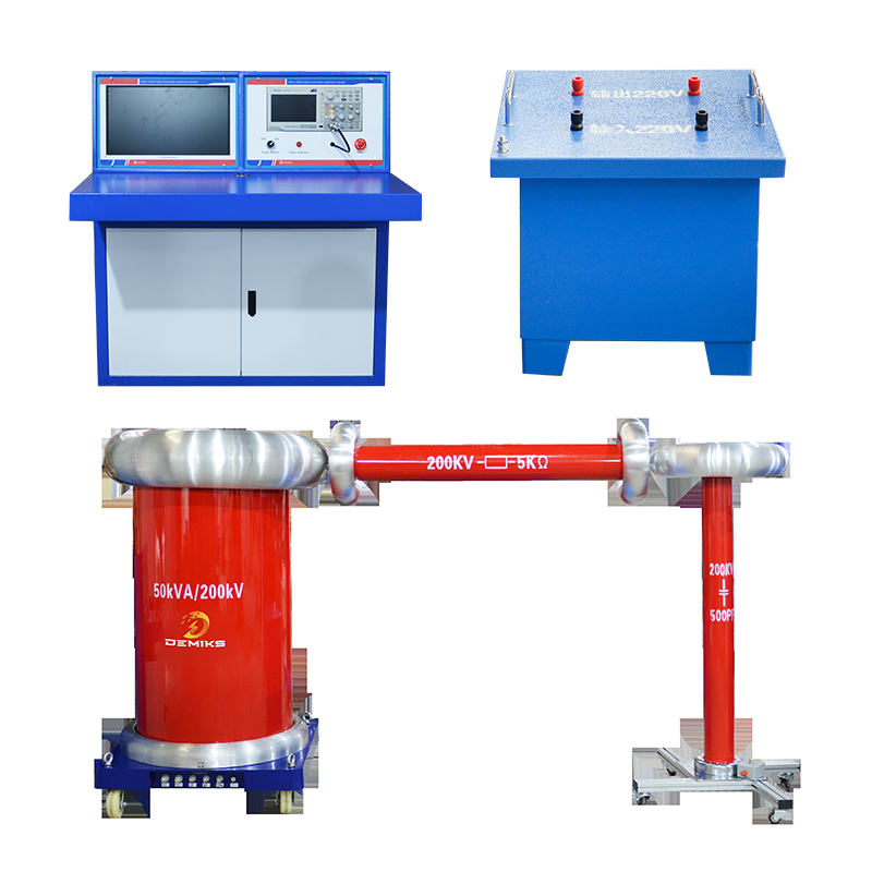
Test Equipment and Systems for Reliable Operation
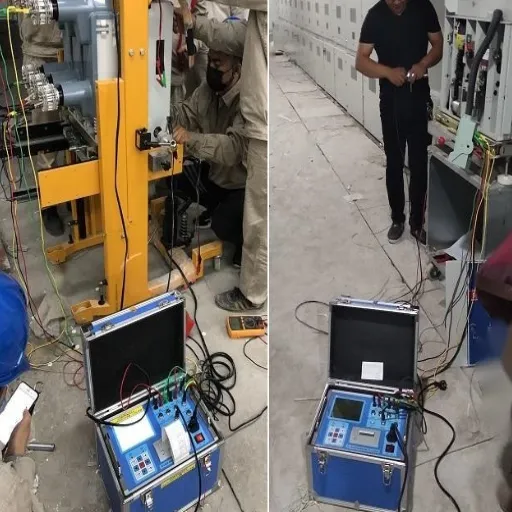
Essential Test Equipment for Circuit Breaker Testing
The selection of test equipment for maintenance and diagnostics on circuit breakers is critical in ensuring the accuracy, reliability, and safety of the operator. Listed below are the major categories of test equipment for complete circuit breaker testing:
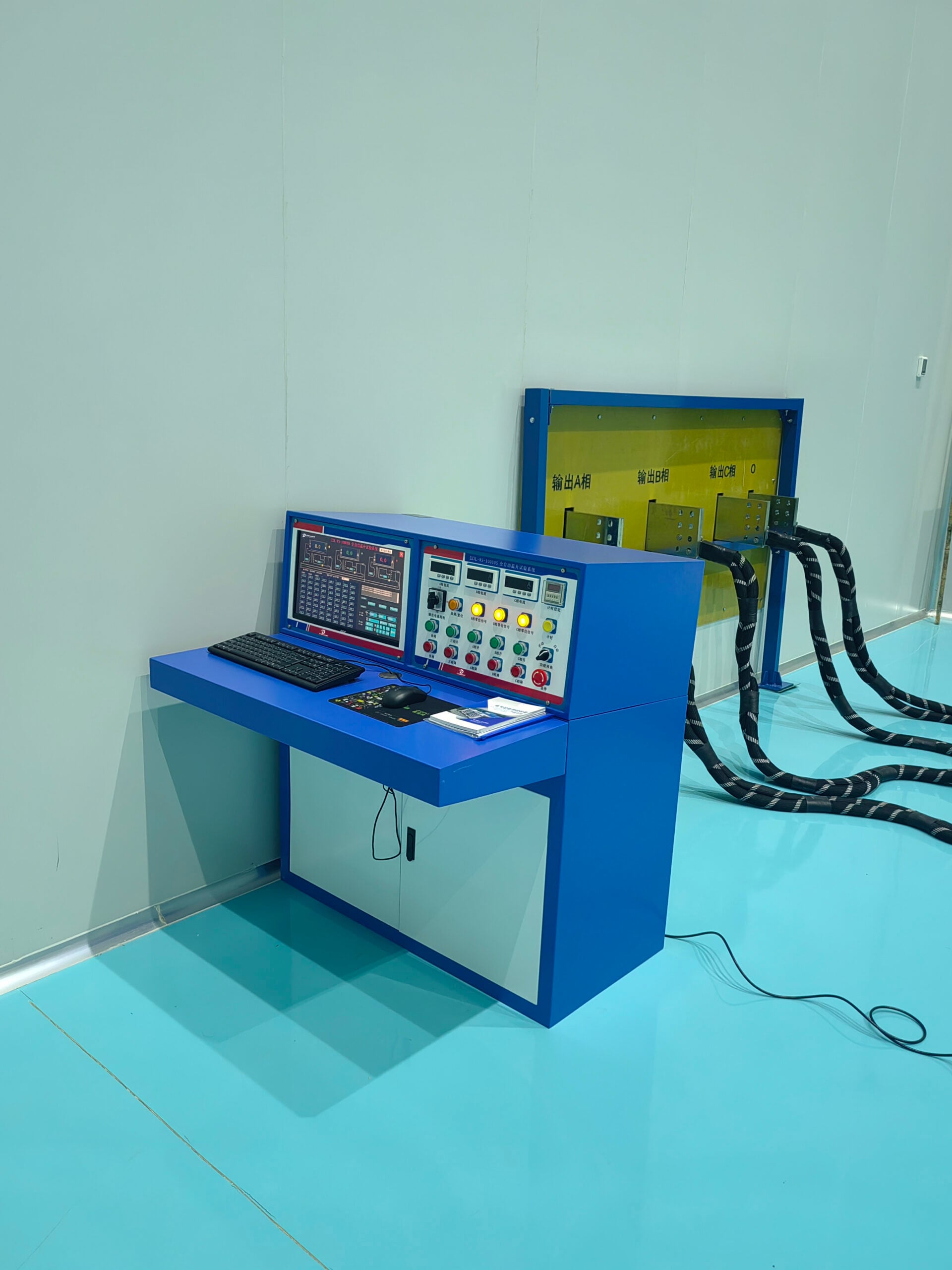
- Primary Injection Test Sets: These injection systems simulate operating conditions by injecting a high current into the breaker’s primary circuit. These test whether the breaker shall carry the fault current under load and cause the operation of its trip mechanisms. Being an essential test for high voltage circuit breakers, even minor deviations in performance may have adverse consequences required.
- Contact Resistance Testers: A resistance tester is used for appropriately measuring resistance across breaker contacts. The instruments operate at high test currents, usually anywhere between 50A and 600A, to detect any abnormally high resistance at the contact points which would cause heating, losses in power, or failure. Mostly, micro-ohmmeters are used for measuring this level of contact resistance, and thereby, breakers are graded in accordance with standards.
- Timing and Motion Analyzers: Accurate timing and motion systems are used to monitor and measure breaker opening and closing times accurately. The analyzers detect any anomalies that occur during operation, which may indicate mechanical delay or misalignment. These diagnostics are essential to prevent a situation of arcing caused by a slightly longer than standard closing of the contacts, which can destroy system integrity.
- Insulation Resistance Tests: Also known as megohmmeters, insulation resistance testers measure the electrical insulation quality within breakers and wiring. High-voltage testing, generally performed at 500V to around 15kV, is conducted to ensure that the insulation can withstand the applied stresses and environmental factors such as moisture and temperature variations.
- Dynamic Circuit Analyzers: These are advanced systems that combine resistance to contact, timing, and motion analyses into a single platform, providing a comprehensive view of breaker performance. It is primarily applicable to complex power systems, where the precise coordination of all electrical elements is necessary.
- Partial Discharge Detectors: Since partial discharge activity constitutes one of the primary indicators of inner insulation assessment, especially for aging breakers, detectors localize specific discharge sites and offer a highly beneficial non-invasive diagnostic capable of preventing catastrophic failures.
Standards Compliance
Resorting to a prestigious test instrument will allow an operator to retrieve high-resolution data and gain insights regarding the health and operating condition of a breaker. The tests are carried out following the ANSI/IEEE C37 series to achieve accuracy and IEC 62271 for global acceptance. Thereby, ensuring this equipment lasts long and operates safely calls for choosing a suitable test series according to the given system requirements and conducting its specified stringent testing procedures upon them.
Establishing an Effective Test System
To set up a test system, the components must be integrated and calibrated with much accuracy. Some advanced diagnostic and condition-assessment devices that should go toward building a capable system are micro-ohmmeters, breaker analyzers, and thermal imagers. All instrumentation should conform to accepted industry standards such as ANSI/IEEE and IEC so that the results can be considered reliable and consistent.
Environmental Control
The testing environment ought to be strategically controlled to minimize any external variables that could alter the results, such as temperature variations and electromagnetic interference. Measures such as electromagnetic shielding and maintaining stable room conditions can be taken to ensure the accuracy of the test.
Data Acquisition Platform
A substantial data acquisition, and analysis platform should then be employed. Such a platform should be capable of monitoring trends in real-time, storing historical trends accurately, and focusing on predictive analytics aimed at identifying proactive solutions to anticipated problems.
Personnel Training
Periodic training and certification of personnel conducting testing is essential. A skilled operator who is aware of the latest methodologies and safety procedures can promptly conduct the test, accurately interpret the results, and thereby maintain system integrity and long-term performance.
Compatibility with software that runs automated test scripts will, undoubtedly, reduce human error and improve performance over time.
Test Equipment Grounding for Safety
Grounding techniques must be applied in all instances for safety and to ensure the satisfactory testing of any electrical or high-voltage system. Faults caused by faulty grounding will result in a transformation in risk hazards, from short circuits and shocks to the danger of surge voltages damaging sensitive equipment or causing electromagnetic interference.
Earth Grounding Principles
Generally, one major method of theory revolves around the concept of earth grounding. Ideal earth grounding, if available, might dissipate excess currents through the earth to have balanced voltage or thereby avoid any overvoltage situations. The resistance that earth presents must be less than 5 ohms for the normal operation of the grounding system, as per accepted safety practices such as IEEE 80. Therefore, such grounding electrodes, usually of copper or galvanized steel, must be installed so as to satisfy this condition, and the resistance must also be tested periodically.
Single-Point Grounding Scheme
Another essential aspect that should not be overlooked is the installation of an effective single-point grounding scheme. This would diminish those ground loop currents that possibly are a source of noise or errors for the measurement systems. For safety’s sake, insulated tools, along with grounding clamps, should be used, while PPE must be selected according to the electrical hazards present.
- Visual inspections will detect corrosion or wear on any grounding components
- Clamp-on ground resistance testing ensures optimal performance throughout their lifecycle
- Fall-of-potential testing provides comprehensive ground system evaluation
- Fault current capacity must be designed and maintained without any degradation
Regular inspection and maintenance are essential considerations for preserving operational integrity. It is further required that the grounding systems be designed and maintained to carry the most significant fault current without any degradation, in order to comply with operational and safety standards.
Best Practices for Circuit Breaker Testing

Scheduling Tests to Minimize Downtime
Disruptions to operational activities are to be minimized while the reliability of the electricity system must not be impaired. Test schedules for circuit breakers should thereby abide by this. The organization needs to analyze its operational cycles in detail to find out times of low demand. Tests carried during planned maintenance windows or late during off-hours hold the least chances of obstructing critical processes. If needed, advanced predictive maintenance methods such as thermal imaging and vibration analysis could be used to isolate potential points of failure before a test, thereby allowing targeted interventions.
Optimal Scheduling Strategy
An alternate way of ensuring availability would be the scheduling of tests wherein a rotating fraction of breakers is tested at a given time. Scheduling decisions are made in a database or another computer system on the basis of data from previous tests, so that the test frequency corresponds to the age, usage, and future environment of the equipment. Operations will be balanced such that system reliability and safety can be ensured.
Creating Comprehensive Test Reports
A comprehensive test report is an essential document used for assessing breaker performance and system reliability. It should adequately record all testing parameters relevant to the considered test, such as test date, equipment identification, and methodology and results with respect to the procedure followed. Parameters necessarily measured and presented in tables include insulation resistance, contact resistance, and tripping time to enable easy comparison against previous fixed standards and values.
Utilizing modern software tools for data capture and analysis will certainly increase report accuracy. Such automation may reduce human error while speeding up the process of generation. Other information, such as trends and tables, increases the ability to detect anomalies or deterioration of the device being measured. To be of maximum value, reports should meet industry and regulatory standards to guarantee transparency and compliance. Correctly generated test reports will assist in concluding and supporting interventions aimed at preventing and/or improving the system.
Regular Maintenance for Enhanced Reliability
A comprehensive maintenance schedule can grant superior reliability to the systems over some period. In the modern maintenance scenario, higher emphasis is on methods like predictive and preventive maintenance; these include sensor-based monitoring and analytics. Through the collection of real-time data, organizations may observe trends in performance or early signs of failure.
Vibration Monitoring
Detecting changes in vibration levels provides early warning signs about mechanical component condition and potential failure modes.
Temperature Analysis
Temperature fluctuation monitoring helps identify thermal issues and contact resistance problems before they become critical.
Energy Consumption
Energy consumption pattern analysis reveals operational efficiency changes and potential system degradation.
Examples of maintenance include observation of changes in vibration, temperature, or energy consumption patterns that may act as warnings regarding the state of machinery or infrastructure. A complete framework allows one to act in time to prevent unplanned downtime and to increase the lifespan of critical components. The system would have to work alongside periodic inspections or calibrations to ensure that it always adhered to specified parameters, thereby reducing risks and maximizing further efficiencies.
Challenges and Considerations in High Voltage Testing
Addressing Common Testing Difficulties
When describing the common trials experienced in high-voltage testing, I would say that one big factor is trying to obtain a precise measurement due to environmental interference. Unpredictable external factors such as humidity suddenly rising at two o’clock in the afternoon, a change in temperature in the room, or the presence of electromagnetic interference outside of the laboratory may give suspicious results. Now, I shall talk about how we take care of these: environmental control and shielding.
Environmental Control Solutions
- Faraday cage implementation to block electromagnetic interference
- Regulated environment testing with controlled temperature and humidity
- Regular calibration checks for test apparatus integrity
- Thorough insulation tests to maintain maximum accuracy
Safety Challenge
The other challenge I often face is maintaining safety during a high-voltage test. Electrical arcing, failure of apparatus, or even exposing men to high voltages constitute some of the dangers involved. My method with regard to safety always includes standardized procedures that maintain clearance distances, utilize personal protective equipment (PPE), and incorporate automatic fail-safes into the testing systems.
Finally, the real technical challenge lies in diagnosing faults of an aging electrical system and its complexity. Many older systems would be void of documentation or proper schematics, making it impossible to perform a thorough analysis to assess their state. Hence, I would utilize higher-order diagnostic tools, including partial discharge measurements and time-domain reflectometry, to drill down into devices and identify the true cause of the problem. These advanced techniques, combined with a very systematic test procedure, methodically track down faults and thereby improve the reliability and reduce downtime.
Ensuring Safety During High-Voltage Testing
Safety comes first in a high-voltage environment and requires strict protocols to be observed. I follow the existing industry-standard codes such as the IEEE and IEC to reduce the risks posed by high-voltage equipment. Testing devices should then be free from calibration errors and well insulated; PPE, including electrically rated gloves, face shields, and flame-retardant clothing, must be used to provide safety to all those involved in the testing. Work areas are then cordoned off with warning signs and barriers, thereby preventing individuals not engaged in test operation from coming any closer.
Before high-voltage testing, I perform a complete risk assessment to identify hazards and apply controls. Grounded test equipment, non-contact testing methods-from checking circuits to ensure they are de-energized before contact, or connecting instruments-must be used. Remote test instruments help operators to remain a safe distance from energized parts during testing. The setup includes real-time monitoring systems that give continuous feedback in case any abnormalities are detected during testing and immediately stop the operation should a fault condition arise.
Training and Preparedness
Finally, in this procedure, particular emphasis is laid upon periodic instructive quality-training sessions and safety drills for all personnel involved in the high-voltage work. This would train my team in emergency response situations and familiarize them with current safety techniques to decrease risks associated with such a situation and increase safety during work operations. To stress the significance of high-voltage testing for high reliability of equipment, such testing should undergo an orderly safety consideration that is proactive in prevention and redundant to protect against loss of life and property.
Future Trends in Circuit Breaker Testing Technologies
Shining advancements emerge when the mind turns to the future of circuit breaker testing technologies, driven by the ever-increasing complexity of electrical grids and the unparalleled need for high-demand applications to be reliable. One of the significant trends is the integration of AI and machine learning into diagnostic systems. Such systems perform real-time analysis of test data, enabling them to report immediate results concerning poor erosion of contacts or inappropriate tripping mechanisms. On another note, AI predictive maintenance modeling becomes a little more sophisticated, enabling one to predict failure before it actually occurs, thereby reducing unexpected downtime and ultimately boosting the reliability of electrical systems.
AI & Machine Learning
Real-time analysis of test data with immediate reporting on contact erosion and tripping mechanisms. Advanced predictive maintenance modeling to prevent failures before they occur.
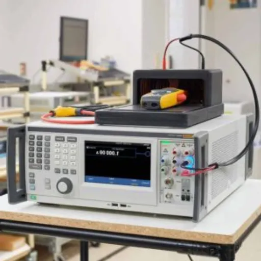
Portable Digital Equipment
Modern circuit breaker analyzers offering portability without compromising diagnostic precision. Features include cloud storage, advanced connectivity, and intuitive interfaces.
Environmental Sustainability
Development of testing technologies for eco-friendly breakers using vacuum or CO2 gas instead of SF6. New protocols being developed to meet performance and environmental criteria.
A further potential area of innovation includes portable and digital testing equipment. Today’s modern circuit breaker analyzers are designed to offer portability without compromising diagnostic precision. They tend to feature advanced add-ons such as cloud storage of test results, advanced connectivity options, and intuitively designed interfaces for ease of use in the field. These enhancements make testing more adaptable and, by extension, simplify compliance with standards for a test technician. I can thus conduct diagnostics using these technologies quickly, even in locations with limited space and resources, thereby ensuring the uninterrupted operation of vital infrastructure.
An external factor also concerns ecological issues affecting circuit-breaker testing. In the interest of global sustainability, greater consideration is given towards creating test technologies for eco-friendly breakers, possibly using vacuum or CO2 gas instead of SF6 gas. Under the new protocols being developed, the alternative solutions must be subjected to testing to comply with the environment directives and performance criteria. Given such advanced technologies and processes, I am in a better position to tackle emerging technical challenges in the energy sector while ensuring a greener environment and sustainable tomorrow.
Reference Sources
- 9 Fundamental Tests For High Voltage Circuit Breakers – Scope TNM
- A Systematic Approach to High-Voltage Circuit Breaker Testing – Omicron Energy
- Circuit Breaker Guidebook Development: 2023 Update – EPRI
- Click here to read more.
Frequently Asked Questions (FAQs)
What are the different types of circuit breakers used in high-voltage applications?
The high-voltage circuit breakers are classified as air-insulated, gas-insulated, and vacuum circuit breakers. Different power system applications usually consist of specialized circuits for reliability and safety considerations. GIS breakers, for instance, are used more where space becomes a constraint in a substation; whereas air-insulated breakers are built outside. Knowledge of these types enables one to choose the correct circuit breaker for his/her operational situation.
How is a circuit breaker test conducted?
The testing of high-voltage circuit breakers involves a process with several specific steps to ascertain that these are reliable and efficient. Typically, the tests include measuring insulation resistance, timing tests, and contact resistance tests. Using test instruments, technicians simulate various operating conditions and assess the circuit breakers’ performance under different circumstances. Thus, thorough scrutiny helps detect problems that may eventually lead to equipment damage or power outages.
What significance does contact resistance hold in the testing of high-voltage circuit breakers?
At the contact surface, the resistance enhances the performance of high-voltage circuit breakers, which helps reliability and operational efficiency. The resistance value at the contacts should be checked whenever the circuit breaker is tested and should be within satisfactory limits. The lower the value, the better the conducting nature, and the lower will be the energy losses and heating. If the contact resistance is measured on a routine basis, it will help to keep the equipment electrically intact and will also increase its service life.
What is the standard testing procedure for high-voltage circuit breakers?
High voltage fragment circuit breakers follow the standard test procedure according to accepted industry standards. For example, these include insulation tests, resistance measurement, operational checks, timing tests, and the like. Recorded performance values indicate high valuing measurements, for such tests require accuracy in providing the voltage and current levels as measured by the standard. The standards provide safe installation and operation guidelines so while meeting these, the circuit breaker shall remain suitable for the power grid.
How can you ensure reliability during testing of high-voltage switches?
To ensure reliability in high-voltage switches, it is necessary to test for the measurement of insulation strength and resistance. Theoretically a good resistance tester tells the affected conditions of arcing and the main contacts. Likewise, tests for opening time and closing time are needed to check the correct operation of load conditions. Regular maintenance and testing solutions greatly promote the performance and life of high-voltage switches.
What are the implications of not carrying out circuit breaker testing?
Inadequate testing of circuit breakers can lead to unwarranted, undesirable consequences, such as physical damage to the equipment and power outages implemented without due notice. When tests are not performed regularly, possible faults remain undetected, resulting in increased downtime at the expense of a narrow commercial angle of safety within the power system itself. Additionally, failure to conduct tests as stipulated in industry standards may result not only in contravention but also in financial penalties. Regular circuit breaker testing becomes a must to maintain operational efficiency and the safety of electrical equipment.