The reliability and safety of electrical power systems depend heavily on the performance of high voltage switchgear. These critical components are responsible for controlling, protecting, and isolating electrical equipment, ensuring the consistent and safe delivery of electricity across networks. Proper testing and maintenance of high voltage switchgear are not only essential for preventing system failures but also for safeguarding personnel working in high-risk environments. This article explores the fundamental practices, advanced techniques, and essential safety protocols involved in maintaining high voltage switchgear. Readers will gain a detailed understanding of how to ensure operational integrity, prolong equipment lifespan, and enhance overall system safety through effective strategies.
What Is High Voltage Switchgear and Why Is It Important?

High voltage switchgear comprises equipment designed to manage and protect electrical systems operating at high voltage levels, typically above 1 kV. Its primary function is to isolate, control, and safeguard electrical circuits during normal operation or in the event of a fault. This equipment is critical for maintaining the reliability and safety of power distribution networks, preventing equipment damage, and ensuring personnel safety. High voltage switchgear is widely used in industries, power plants, and substations, where it enables efficient handling of large electrical loads while mitigating risks associated with high voltage systems.
Understanding Switchgear Systems
Switchgear systems are integral to electrical power systems, providing the framework for monitoring, controlling, and protecting power flows within an electrical network. These systems consist of various components, such as circuit breakers, disconnectors, and fuses, which serve to isolate electrical circuits and protect equipment during faults or maintenance. Modern switchgear technologies can be classified into low voltage (LV), medium voltage (MV), and high voltage (HV) categories, depending on the application and voltage level requirements.
The primary functions of switchgear include ensuring uninterrupted power supply by addressing overloads or short circuits, facilitating safe maintenance by isolating circuit sections, and maintaining system stability. Advances in switchgear design now feature innovations such as arc-resistant enclosures, improved insulation techniques, and remote monitoring capabilities, enhancing both functionality and safety. These systems are deployed across industrial facilities, commercial buildings, and utilities, playing a vital role in managing complex electrical infrastructures reliably and efficiently.
The Role of High Voltage in Power Systems
- Efficient Power Transmission: High voltage reduces energy losses during the transmission of electricity over long distances by minimizing current, which subsequently decreases resistive losses in conductors.
- Optimal Resource Utilization: Implementing high voltage systems allows for smaller conductor sizes and reduced material costs, improving economic efficiency in power line construction.
- Grid Stability: High voltage facilitates the integration of decentralized energy sources, such as wind and solar farms, into the grid, enhancing overall stability and operational reliability.
- Enabling Long-Distance Transmission: High voltage lines make it possible to transmit electricity across vast geographic areas, ensuring regions far from power generation sites have access to electricity.
- Supporting Bulk Power Transfers: High voltage systems accommodate the transfer of large quantities of power, which is critical for meeting industrial and urban energy demands.
- Interconnection of Grids: High voltage enables the connection of regional power grids, allowing for the sharing of resources, improving redundancy, and enhancing resiliency in case of local faults or failures.
- Reduction of Voltage Drops: Operating at high voltage levels minimizes voltage drops across transmission lines, ensuring consistent and reliable energy delivery to end-users.
- Facilitating Technological Advancements: The use of high voltage has driven innovations in insulation materials, switchgear technology, and system protection mechanisms, supporting the evolution of modern electrical infrastructure.
Key Components of Voltage Switchgear
Voltage switchgear consists of several critical components, each serving a specific function to ensure the safe and efficient operation of electrical systems. Below are the primary components and their technical parameters:
- Circuit Breakers: Designed to interrupt current flow during faults, circuit breakers are rated based on parameters such as breaking capacity (e.g., 25 kA to 50 kA) and operational voltage (e.g., 11 kV, 33 kV, or 132 kV systems). They safeguard equipment by isolating faulted sections of the network.
- Disconnectors (Isolators): These manually or motor-operated devices are used to ensure a visible disconnection point for maintenance. They operate at nominal voltage levels and are not designed for switching under load.
- Current Transformers (CTs): CTs monitor and step down high current levels to manageable values for measurement and protection systems. Typical ratings include primary current (e.g., 600 A) and secondary current (e.g., 1 A or 5 A). Accuracy is critical, with classes such as 0.2 or 5P10 for protection applications.
- Voltage Transformers (VTs): These step down high voltage levels to lower, measurable levels, ensuring accurate voltage monitoring and relay operation. Key specifications include primary voltage (e.g., 11 kV) and secondary voltage (e.g., 110 V).
- Busbars: Conductive elements that distribute power between various switchgear components. Often made of copper or aluminum, they are rated based on current-carrying capacity (e.g., 2,000 A to 5,000 A) and thermal withstand.
- Protective Relays: These devices detect abnormal system conditions and initiate breaker operation. They are calibrated for specific fault conditions such as overcurrent, earth fault, or differential protection.
- Earthing Switches: Responsible for safely grounding specific portions of the switchgear during maintenance. They have short-circuit current ratings consistent with circuit breakers.
- Enclosures: Comprising metal or composite materials, enclosures house all switchgear components and provide physical protection, IP ratings (e.g., IP4X), and environmental resistance.
Each component is engineered to ensure uninterrupted operation, facilitate maintenance, and enhance overall safety within high-voltage and medium-voltage systems. Proper specification and configuration of these elements are essential to address unique system requirements.
How is High Voltage Switchgear Tested?
High voltage switchgear is tested through a comprehensive series of assessments to ensure operational reliability, safety, and compliance with industry standards. These tests include:
- Dielectric Tests: Verifies insulation performance and ability to withstand overvoltages.
- Temperature Rise Tests: Ensures that components operate safely under rated load conditions without overheating.
- Mechanical Operation Tests: Confirms the durability and functionality of switching mechanisms over repeated operations.
- Short-Circuit Withstand Tests: Assesses the switchgear’s ability to handle extreme fault currents without failure.
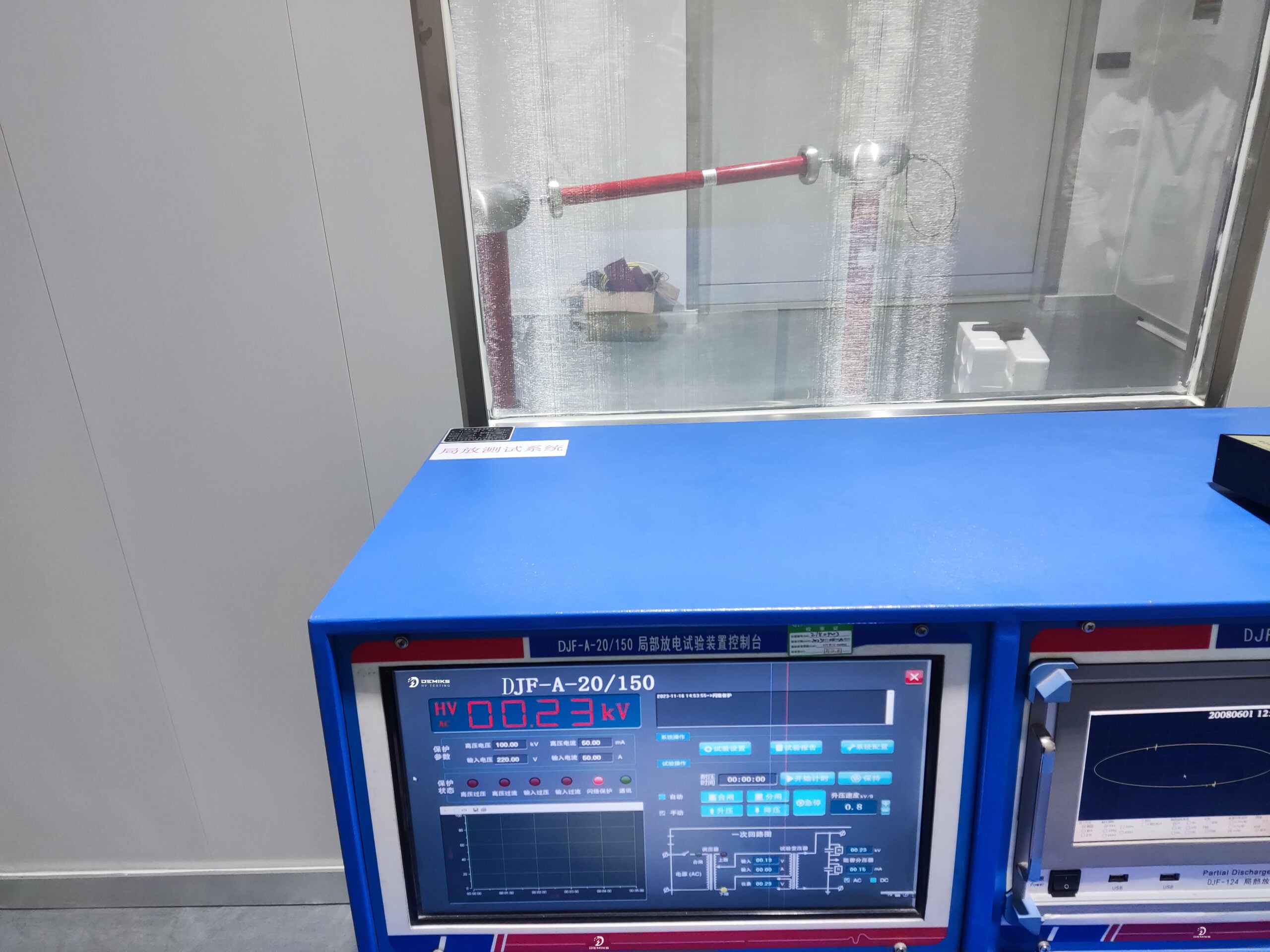
- Partial Discharge Tests: Detects insulation defects and assesses the quality of insulation materials.
- Functional and Interlock Tests: Validates that control circuits, interlocking systems, and auxiliary devices operate correctly.
These tests are executed according to standardized guidelines such as IEC 62271, ensuring switchgear performance aligns with design and operational criteria under real-world conditions.
Understanding Type Tests for Switchgear
Type tests for switchgear are critical evaluations conducted to verify the performance, safety, and reliability of the equipment under specific conditions. These tests are designed to ensure compliance with industry standards, such as IEC 62271, and to certify that the switchgear meets functional and safety requirements before being deployed in real-world applications. Below are the key type tests and their corresponding technical parameters:
1. Dielectric Type Test: This test assesses the switchgear’s ability to withstand overvoltage stresses without insulation breakdown. It includes:
-
- Lightning Impulse Voltage Test: Verifies performance under simulated lightning conditions. For example, a 36 kV switchgear should withstand impulses of up to 170 kV peak.
- Power Frequency Voltage Test: Determines insulation strength under steady-state AC overvoltage. A typical value for a 36 kV system is 70 kV for 1 minute.
- Temperature Rise Test: Ensures that components remain within permissible temperature limits during normal operation. Parameters include:
- Maximum allowable temperature for current-carrying parts, e.g., 105°C for copper or aluminum conductors.
- Temperature rise limits specified by IEC standards, such as 65°C for conductors under full rated load.
- Short-Circuit Withstand Test: Evaluates the mechanical and thermal resilience of the switchgear under short-circuit conditions. Key parameters include:
- Rated short-time withstand current (e.g., 25 kA for 3 seconds for medium-voltage switchgear).
- Peak withstand current often calculated as 2.5 times the rated short-time current.
- Mechanical Operation Test: Validates the durability and mechanical reliability of moving parts. The switchgear is actuated multiple times (e.g., 2,000 operations) to ensure consistent performance.
- Internal Arc Test: Focused on personnel safety, this test simulates the impact of internal arc faults to evaluate the switchgear’s ability to contain and redirect fault energy. For instance, a typical internal arc classification might be IAC AFLR for a duration of 1 second at 40 kA.
By combining these results, manufacturers can certify that the switchgear will perform reliably under a range of operational stresses. The detailed parameters provided above align with internationally recognized benchmarks to ensure consistency and safety in various applications.
Importance of Voltage Withstand Tests
Voltage withstand tests are critical in evaluating a switchgear’s ability to endure specified overvoltage conditions without failure. These tests help verify the insulation’s strength against short-term electrical stress, ensuring the equipment can operate reliably under normal and fault conditions. Typically, both AC and impulse voltage tests are performed, simulating operational scenarios such as power surges or lightning strikes. International standards such as IEC 62271-1 define the procedures and voltage levels for these tests to maintain consistency across applications. Successfully passing these tests confirms the durability and robustness of the insulation system, reducing the risk of electrical breakdowns and enhancing user safety. Furthermore, voltage withstand tests provide vital assurance of long-term performance, particularly in high-stress industrial environments.
Common Electrical Tests for Switchgear
|
Test Name |
Purpose |
Key Parameters |
|---|---|---|
|
Insulation Resistance Test |
Assess insulation integrity |
Resistance in megaohms (MΩ) |
|
Dielectric Withstand Test |
Verify insulation strength under high voltage |
Applied test voltage |
|
Contact Resistance Test |
Measure resistance of conductive joints |
Milliohms (mΩ), contact pressure |
|
Temperature Rise Test |
Evaluate heat generation in conductive parts |
Temperature increase (°C) |
|
Detect defects in insulation materials |
Discharge magnitude in picocoulombs (pC) |
|
|
Short-Circuit Test |
Verify performance under high fault current |
Test current, duration, and withstand ability |
|
Functional & Operational Test |
Ensure switchgear operates as designed |
Correct functionality observed |
|
Current Injection Test |
Validate protection relay and circuit behavior |
Injected current amplitude |
|
Visual & Mechanical Inspection |
Check for physical defects and alignment |
General condition, alignment |
|
Overload Test |
Simulate prolonged high load to ensure integrity |
Rated current and duration |
What are the Different Types of Tests for Switchgear?
Switchgear undergoes various types of electrical tests to ensure safety, reliability, and conformance to standards. These tests can generally be categorized as follows:
- Dielectric Tests: Assess the insulation strength of the switchgear under high voltage conditions to ensure it can handle specified operating voltages without breakdown.
- Thermal Tests: Measure the heat rise in components during normal operating conditions to verify that the switchgear can manage thermal stress effectively.
- Mechanical Tests: Validate the durability and proper operation of moving parts, including circuit breakers, disconnectors, and other mechanical components.
- Short-Circuit Tests: Simulate fault conditions by applying high currents to confirm the ability of the switchgear to interrupt and contain faults without damage.
- Partial Discharge Tests: Detect localized insulation weaknesses by measuring partial discharges, helping to identify potential long-term insulation issues.
- Operational Tests: Ensure that all auxiliary and control circuits, protection mechanisms, and communication systems perform reliably under designated conditions.
These tests are carried out according to standards like IEC 62271 or ANSI/IEEE guidelines, providing a comprehensive evaluation of the performance and safety of switchgear systems.
Insulation Resistance and Its Role
Insulation resistance plays a critical role in ensuring the safe and reliable operation of electrical equipment, including switchgear systems. It measures the ability of an insulating material to resist the flow of leakage current, which is vital for preventing short circuits, electrical shocks, and equipment failures. The higher the insulation resistance, the better the material’s performance in isolating live electrical components.
Parameters to Consider in Insulation Resistance Testing:
1. Test Voltage:
-
- Typical values range from 500V to 5kV DC, depending on the equipment rating and voltage class.
- For medium-voltage switchgear (up to 36kV), 1kV or 2.5kV DC is commonly used.
- Acceptable Insulation Resistance Values:
- It varies based on the system but generally follows the rule of thumb of \(1 M\Omega\) per kV of operating voltage, with a minimum threshold of \(1 M\Omega\).
- For high-voltage systems, insulation resistance values may exceed \(100 M\Omega\) due to stricter safety requirements.
- Testing Standards:
- Adherence to IEC 60060 or IEEE 43 ensures consistency and accuracy in evaluating insulation resistance.
- Environmental Conditions:
- Temperature, humidity, and contamination can influence readings significantly. Testing should factor in conditions and, if necessary, apply correction factors as provided in standards.
Regular insulation resistance testing identifies degradation due to aging, moisture ingress, or contaminants and is an essential component of preventative maintenance programs in electrical systems.
Conducting Resistance Tests
Conducting resistance tests involves systematic steps to ensure accurate and reliable results while adhering to safety standards. Firstly, disconnect the equipment under test from the power source to prevent potential hazards and ensure no residual voltage is present. Use a calibrated insulation resistance tester, typically a megohmmeter, and select the appropriate test voltage based on equipment ratings and applicable standards. Connect the test leads to the equipment terminals, ensuring firm and clean contact points to avoid erroneous readings.
Begin the test by applying the selected voltage for a specified duration, usually 1 minute, as per industry standards like IEEE 43 or IEC 60034-27. Observe and record the resistance values while monitoring for signs of instability or sudden drops, which may indicate insulation weakness. If polarization index (PI) testing is required, measure the resistance at both 1 minute and 10 minutes to calculate the PI ratio, providing insights into moisture or contamination levels.
After testing, safely discharge any stored electrical energy in the equipment before removing the test leads. Analyze results against manufacturer specifications or reference values to determine the insulation condition. Regular testing intervals should align with maintenance schedules to establish performance trends and identify early signs of insulation deterioration.
Voltage Withstand Tests and Their Importance
Voltage withstand tests, also known as dielectric withstand tests, are critical for assessing the integrity and reliability of insulation within electrical equipment. These tests involve applying a high voltage—typically higher than the equipment’s normal operating voltage—for a specified duration to determine whether the insulation can endure without electrical breakdown.
Key Technical Parameters:
- Test Voltage: Generally, test voltages range from 1.5 to 2 times the equipment’s rated voltage. For example, equipment rated at 1 kV may undergo testing at 1.5 kV to 2 kV.
- Test Duration: Industry standards such as IEC 60243 or IEEE guidelines often recommend a duration of 1 minute for the application of the test voltage.
- Leakage Current: Measure the current that flows through the insulation during the test. Excessive leakage current may indicate compromised insulation.
- Environmental Conditions: Parameters such as temperature (e.g., 20°C to 30°C) and humidity (e.g., below 70%) should be controlled during testing to ensure accurate measurements and avoid external influences.
Importance of the Test:
Voltage withstand tests play a crucial role in identifying potential faults in insulation, which could lead to dielectric failure, short circuits, or equipment malfunction. By performing these tests, technicians can ensure compliance with safety standards, prevent costly downtime, and enhance equipment longevity. Regularly conducting voltage withstand tests as part of a predictive maintenance program helps establish baseline performance and detect early signs of degradation, ensuring the safe and reliable operation of electrical systems.
How to Conduct Effective Switchgear Maintenance?

Steps for Effective Switchgear Maintenance
- Visual Inspection – Begin by conducting a thorough visual examination of the switchgear. Check for signs of physical damage, corrosion, loose connections, or contamination such as dust, dirt, or moisture.
- Cleaning – Clean the components using approved methods and materials to remove accumulated dirt and debris, which can cause overheating or tracking.
- Tightening Connections – Ensure all connections are securely tightened to prevent issues like arcing or overheating caused by loose components.
- Insulation Testing – Perform insulation resistance tests to verify the integrity of the insulation material and identify potential leakage currents or degradation.
- Functional Testing – Test critical components, such as circuit breakers, relays, and protective devices, for proper functionality under operational conditions.
- Lubrication – Lubricate moving parts, such as hinges and mechanisms, to reduce wear and ensure smooth operation.
- Thermal Imaging – Use infrared thermal imaging to identify abnormal temperature patterns that may indicate overloaded circuits, loose connections, or failing components.
- Compliance Verification – Verify that all maintenance activities meet the manufacturer’s guidelines and align with applicable regulatory requirements and standards.
- Documentation – Maintain detailed records of all maintenance activities, test results, and observations to support trend analysis and the overall reliability of the electrical system.
By adhering to these steps, technicians can ensure switchgear operates efficiently, safely, and reliably over its lifespan.
Preventive Maintenance Services for Reliability
Preventive maintenance services are designed to proactively identify and resolve potential issues within critical electrical systems, ensuring operational safety and efficiency. By implementing a structured maintenance plan, I focus on minimizing downtime and extending the equipment’s service life. This approach typically involves scheduled inspections, thorough testing, and necessary calibrations in accordance with industry best practices and manufacturer specifications. My priority is to enhance the system’s overall reliability through meticulous attention to detail, compliance with regulatory standards, and a commitment to delivering long-term value for clients.
Inspection and Testing of Electrical Connections
When inspecting and testing electrical connections, I prioritize ensuring operational safety, adherence to standards, and optimal system performance. My process begins with a visual inspection to identify signs of wear, corrosion, overheating, or loose connections. Using tools such as thermal imaging cameras, I check for hot spots indicative of potential faults. Electrical testing involves precise measurements, including verifying voltage levels, current integrity, and resistance values using multimeters and ohmmeters.
Key technical parameters I assess include:
- Voltage Levels: Matching expected ratings (e.g., 120V, 240V, or 480V as applicable).
- Connection Resistance: Ensuring resistance is below 1 milliohm for most critical connections to prevent power losses.
- Thermal Limits: Investigating areas with temperatures exceeding 140°F (60°C), which could indicate overheating.
My approach integrates compliance with standards such as NFPA 70E and IEC guidelines, balancing safety and performance while preempting failures through detailed diagnostics and proactive maintenance.
Manufacturer’s Guidelines for Maintenance
Manufacturers emphasize adherence to prescribed maintenance intervals and protocols to ensure the longevity and reliability of equipment. Key recommendations include:
- Routine Inspections and Testing: Perform regular visual inspections and conduct diagnostic tests, such as insulation resistance testing and thermographic scanning, to detect early signs of wear or overheating.
- Cleaning and Lubrication: Maintain cleanliness by removing dust, debris, and contaminants from components. Apply manufacturer-approved lubricants on moving parts to reduce friction and prevent mechanical failures.
- Component Tightening and Replacement: Ensure all electrical connections and mechanical joints are secure. Replace damaged or worn components, such as gaskets, bearings, or connectors, using genuine manufacturer parts to maintain system integrity.
- Calibration and Software Updates: As indicated in the manual, periodically calibrate the equipment’s sensors, meters, and controllers. Apply any manufacturer-issued firmware or software updates to improve operation and mitigate possible weaknesses.
- Environmental Control: Monitor and control surrounding conditions like humidity, temperature, and vibration to mitigate external factors that may negatively impact equipment.
System operators can reduce system downtime, improve productivity, and extend system service life by following the procedures outlined. For specialized procedures or clarifications, always check the equipment manual and reach out to the manufacturer’s support.
What Safety Measures Should be Taken During Switchgear Testing?

Safety Measures During Switchgear Testing
- Personal Protective Equipment (PPE): Ensure all personnel wear appropriate PPE, including insulated gloves, face shields, and flame-resistant clothing, to protect against electrical arcs and potential hazards.
- System De-energization: Verify that the switchgear is properly de-energized and isolated from all power sources before commencing testing operations.
- Lockout/Tagout (LOTO): Implement strict lockout/tagout procedures to prevent accidental re-energization of the system during testing.
- Proper Grounding: Ensure all equipment is adequately grounded to discharge residual energy and minimize the risk of electrical shocks or arcs.
- Use of Insulated Tools: Employ tools with proper insulation ratings designed for high-voltage environments to reduce the likelihood of electrical contact.
- Environmental and Proximity Hazards: Maintain a safe working distance from live components, and confirm the testing area is free of water, debris, or conductive materials.
- Trained Personnel: Only qualified and trained professionals should conduct switchgear testing, given the complexity and inherent risks of the task.
By adhering to these safety measures, the risk of accidents and equipment damage can be significantly reduced, ensuring safe and effective switchgear testing procedures.
Ensuring Safe High Voltage Testing Practices
To ensure safe high voltage testing practices, I would first ensure that all testing equipment is thoroughly inspected for any signs of wear or damage before use. I would also verify that personal protective equipment (PPE) suitable for high voltage environments is worn at all times, including insulating gloves, boots, and flame-resistant clothing. Additionally, I would confirm that the work area is organized and free of hazards, with clear isolation of the equipment under test to avoid unexpected contact with live components. Finally, I would ensure that all personnel involved are qualified, have appropriate training, and strictly adhere to standardized safety procedures and regulations established by industry guidelines. These steps are essential for mitigating risks associated with high voltage testing.
Interlocks and Their Role in Safety
Interlocks are critical safety mechanisms designed to prevent accidents and ensure safe operation during high voltage testing or other hazardous procedures. Below is a detailed list of interlocks and their roles:
- Mechanical Interlocks
These interlocks use physical barriers or mechanisms to restrict access to hazardous areas unless specific conditions are met. For example, a door may remain locked until the high voltage equipment is de-energized.
- Electrical Interlocks
Electrical interlocks cut off power to a system when safety conditions are violated. For instance, opening a panel or door can automatically disconnect the power supply, preventing exposure to live components.
- Keyed Interlocks
A keyed system ensures that only authorized personnel can access restricted equipment. Keys are often sequentially operated, ensuring specific operational steps are followed before high voltage systems can be energized.
- Software or Logic-Based Interlocks
These interlocks are implemented through software programming or logic controllers. They monitor safety conditions in real-time and intervene by shutting down operations if predefined thresholds, such as temperature or voltage limits, are exceeded.
- Pressure or Environmental Interlocks
These systems are triggered by environmental conditions, such as excessive pressure, temperature, or humidity. They prevent equipment operation in conditions outside specified safe parameters to minimize risk.
- Personnel Safety Interlocks
Designed to protect human operators, these interlocks include systems like emergency stop buttons, motion sensors, or proximity detectors that halt operations when someone enters a hazardous zone.
- Time-Delay Interlocks
These interlocks enforce a delay between critical operations, ensuring sufficient time for hazardous elements, such as residual voltage, to dissipate before personnel access the equipment.
Implementing and maintaining interlocks is essential for guaranteeing safety in high-risk environments. Their combined functionality creates redundant layers of protection, minimizing the likelihood of accidents and ensuring compliance with safety standards.
Emergency Procedures and Safety Protocols
Emergency procedures and safety protocols are structured guidelines designed to mitigate risk, protect personnel, and ensure the systematic handling of hazardous situations. Effective protocols typically incorporate a clear chain of command, detailed communication strategies, and predefined steps to address emergencies. Key components include:
- Incident Identification: Early detection of an emergency is critical. This involves recognizing warning signs such as abnormal system performance, alarms, or hazardous material leaks.
- Communication: Establish efficient communication channels to alert personnel and relevant emergency response teams immediately. Use alarms, public announcements, and digital notifications to disseminate information rapidly.
- Evacuation Procedures: Clearly mark exits and evacuation routes. Conduct regular drills to ensure employees are familiar with escape paths and assembly points.
- Use of Emergency Equipment: Provide accessible safety equipment such as fire extinguishers, chemical spill kits, and first aid supplies. Train staff to handle these tools effectively.
- Shutdown and Isolation: For high-risk facilities, define a process to safely power down machinery, isolate hazardous systems, and prevent further escalation.
- Post-Emergency Evaluation: Document the incident thoroughly, identify causes, and implement corrective actions to enhance future safety measures.
By adhering to these protocols, organizations ensure preparedness, minimize harm, and comply with regulatory standards for workplace safety.
Reference Sources
-
Top 5 Essential Testing & Maintenance Requirements For Switchgear – A detailed guide on routine tests and maintenance practices.
-
Switchgear Maintenance and Repair Service by RESA Power – Insights into professional maintenance and repair services for switchgear.
-
Maintenance and Troubleshooting Guidelines for High Voltage Switchgear – Comprehensive guidelines for regular inspections and troubleshooting.
-
Quick Guide to Switchgear Testing – Covers mandatory testing requirements based on IEC standards.
-
Switchgear Testing & Maintenance by Independent Testing – Focuses on ground resistance, grid integrity, and compliance checks.
Frequently Asked Questions (FAQs)
Q: What is electrical switchgear and why is it important?
A: Electrical switchgear refers to the combination of electrical disconnect switches, fuses, or circuit breakers used to control, protect, and isolate electrical equipment. It is crucial for ensuring safety and reliability in electrical systems by managing and distributing electrical power efficiently.
Q: What is the difference between low voltage switchgear and medium and high voltage switchgear?
A: Low voltage switchgear operates at voltages up to 1,000 volts, while medium and high voltage switchgear handle voltages above 1,000 volts. The latter is designed to manage higher system voltage levels, offering more robust protection and control for larger electrical systems.
Q: How often should switchgear be tested?
A: Switchgear should be tested regularly as part of routine maintenance to ensure it operates safely and efficiently. The frequency of testing may vary based on the manufacturer’s guidelines, the type of switchgear, and the operating environment, but annual testing is commonly recommended.
Q: What are some common tests performed on high voltage switchgear?
A: Common tests for high voltage switchgear include insulation resistance testing, withstand voltage testing, contact resistance measurement, and secondary or primary injection testing. These tests help ensure the equipment can handle the designated test values safely.
Q: Why is it important to de-energize equipment to allow work on switchgear?
A: De-energizing equipment is crucial to ensure the safety of personnel performing maintenance or repair on switchgear. It helps prevent accidental contact touch with live components, reducing the risk of electrical shock or arc flash incidents.
Q: What role do certification bodies play in switchgear maintenance?
A: Certification bodies ensure that switchgear meets industry standards, such as those set by NEMA or ANSI. Their approval provides assurance that the equipment is safe, reliable, and compliant with regulatory requirements, which is essential for both routine maintenance and operational integrity.
Q: How does SF6 gas contribute to the operation of GIS switchgear?
A: SF6 (sulfur hexafluoride) is used as an insulating and arc-quenching medium in GIS (Gas Insulated Switchgear). It enhances the safety and efficiency of the switchgear by providing excellent dielectric properties, which allow for compact designs and reliable operation even in challenging environmental conditions.
Q: What safety measures should be considered during the maintenance of switchgear?
A: Safety measures during the maintenance of switchgear include ensuring adequate clearance around equipment, using proper personal protective equipment (PPE), and following lockout/tagout procedures to de-energize circuits. Additionally, only trained personnel should perform maintenance to mitigate risks associated with high-voltage systems.
Q: What is the significance of the movement of contacts in vacuum circuit breakers?
A: The movement of contacts in vacuum circuit breakers is critical for interrupting the current flow and extinguishing arcs. Vacuum circuit breakers use a vacuum to quench arcs, offering rapid arc extinction and minimal contact wear, which enhances the longevity and reliability of the switchgear.
Q: How do busbar trunking systems integrate with switchgear?
A: Busbar trunking systems distribute electrical power from switchgear to various parts of a facility. They provide a reliable, efficient, and flexible means of power distribution, reducing the need for extensive cabling and allowing for easy modifications or expansions in the electrical network.