Today’s infrastructure relies on electrical systems as the backbone of the system since they are integrated in residential houses and even sophisticated industrial plants. Ensuring their safety, reliability, and efficiency are fundamental because of the need for their functionality and electrical testing equipment offers such ease in this regard. This guide aims to cover all the relevant tools and instruments for assessing and maintaining an electrical system. Every professional, irrespective of their position as an expert electrical engineer or a newcomer to the field, would be better served with a basic understanding of the application and functionalities of these devices so as to make an educated choice. This article teaches the core functionalities, use cases, and critical factors which must be put into consideration for the proper selection of testing equipment using multimeters, insulation testers and advanced power quality analyzers as a reference. Equipments which help in optimizing the electrical performance while maintaining safety standards will also be discussed.
What are the Different Types of Electrical Testing Equipment?
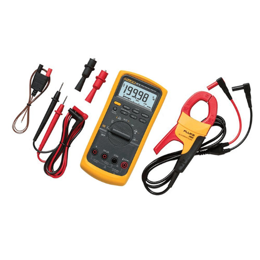
Such equipment may be categorized as follows:
- Multimeters
In diagnosing electrical issues, circuits testing and continuity verification on both residential and industrial scales, multimeters easily rank as some of the most efficient tools due to their versatility since they can measure voltage, current and resistance.
- Insulation Testers
Insulation testers diagnose the structural problems with insulation in wires and electrical systems. They are key apparatus for detecting problems like insulation breakdown which causes faults or safety issues.
- Clamp Meters
Clamp meters are an example of an instrument used for measuring current in an electrical line that cannot be switched off. They are used where it is impractical to break the circuit.
- Power Quality Analyzers
These advanced tools evaluate the quality of electrical power in a system by detecting voltage sags, harmonic distortions, imbalances, and more. They are often used in factories and other industrial workplaces for productivity purposes.
- Circuit Testers
As their name suggests, these tools are the basic type of testers that check for electrical current at sockets, outlets, and circuits. Their simplicity makes them ideal for maintenance work.
Each of the tools discussed provides accurate measurements of diagnostics to protect an electrical system’s safety and performance.
Understanding Multimeters and Their Uses
Electricians and hobbyists require precise measuring instruments such as Voltmeter, Ammeter, Ohm Meter, which can be integrated in one device known as multimeters. They come in two interfaces, analog and digital. Because they offer convenience in portability and functionality, digital multimeters or digital multimeters (DMMs) became more popular.
The most common applications for a multimeter include troubleshooting, testing a circuit, and confirming whether or not it meets certain safety guidelines. A multimeter, for example, can evaluate whether a power supply is operating by assessing its voltage output. Current measurement also aids in assuring circuits are not oversubscribed so that systems can function without risking failure. Testing resistance is important in finding damaged parts or confirming proper and exact connections within a system. More advanced models of multimeters increase their usefulness by including measuring capacitance, frequency, or even temperature, thus aiding in the thorough diagnosis of intricate electronics. Multimeters that require constant trust for precision must be understood deeply and recalibrated regularly to ensure the measurements will be consistent over time.
Types of Electrical Testers for Various Applications
Just as there are different working types of systems for a given electrical component, there are unique electrical testers crafted for every system. Outlined below are the various tester types used and their relative applications.
- Voltage Testers
Voltage Testers assess the level of current in a circuit, and can confirm whether it is active or dormant. They can be divided into two non-contact categories: voltage testers and contact testers. Non-contact voltage testers (NCVTs) are very handy when it comes to identifying wires that are live, as they ensure that electric shocks do not cause harm. There are advanced NCVT models that can measure differences in voltage within specific ranges and diagnose in reactive and proactive modes in homes and industries.
- Continuity Testers
Continuity testers serve the unique purpose of ascertaining if there is a complete circuit or wire which forms a closed circuit for current to flow freely. During the installation processes of electrical circuits, these testers flag the users with alerting audio and visual signals whenever there is continuity detected aiding in the location of open circuits or breaks.
- Multimeters
The best example of a versatile equipment is multimeters as they measure voltage, measure current flowing through a resistor, and resistance all together. Modernized digital multimeters also have additional capabilities where they can measure temperature, capacitance, and even frequency thus proving to be very important advanced diagnostic electric multi-attach equipment. Complex system professionals dealing with high precision measuring systems are served by higher end multimeters which guarantees exact measurements.
- Clamp Meters
Clamp meters incorporate features of a multimeter, as well as the ability to measure current without breaking a circuit. This type of tester is incredibly useful model when the scenario for use requires not breaking the circuit such as industrial machines or high-current installations.
Choosing the appropriate electrical tester for any given task relies heavily on the particular needs of the task at hand. It is equally important to follow best practices, follow the instructions, perform regular maintenance as well as calibration checks for accuracy and safety.
Key Features of Electrical Testing Tools
Like any other field, electrical testing requires tools that have been designed specifically to provide the utmost precision, safety, and efficiency. Here is an outline of the most critical features that can be found in electrical diagnosing tools:
- Multifunctionality
With the advancement of technology, electrical testers have become versatile to the point where the tester can measure voltage, current, and check for continuity as well, all in one device. This also increases the efficiency of the operations being conducted.
- Auto-Ranging Capability
Advanced testers are auto ranging which selects the measurement range for a particular signal automatically. This feature reduces tester errors and streamlines the process especially in in-depth system analysis.
- Non-Contact Voltage Detection
A safety-enhancing non-contact voltage (NCV) function allows classification of live circuits to be done remotely and without direct exposure to open wires. This is extremely crucial in high voltage environments.
- True RMS Measurement
Advanced testers frequently have the capability of True RMS (Root Mean Square) measuring, which allows precise measurements of both linear and non-linear loads. This is helpful when studying circuits with variable frequency drives or those that have harmonics.
Using these capabilities, tools help ensure safety and reliability during electrical diagnostics while also streamlining workflows for the users. Relevant features should be chosen based on the intended purpose to optimize their usefulness and provide adherence with safety requirements.
What is Insulation Resistance Testing?

Insulation resistance testing is a measurement process of current leakage and isolation current. This method measures the resistance between lines and the isolation material. Through proper electrical insulation, resistance to current leakage while utilizing a high voltage source is achieved. Proper insulation provides high resistance while lower resistance indicates some form of damage or contamination that can lead to structural or safety issues. Issues such as electrical faults and short circuits can arise easily without timely troubleshooting.
Purpose of Insulation Testing in Electrical Systems
Testing of insulation, also known as infallible testing, aims to ensure safety from any electrical incidents, reliability of the system, and safety during operations maximally. Over time, things like the ingress of moisture, changes in temperature, chemicals, or mechanical stress can damage the insulation and result in reduced performance or total breakdowns of systems. Technicians are able to measure the insulation resistance, which shows signs of wear and tear, such as faults, leakage currents, or something that may try to compromise the system or endanger personnel.
How to Measure Insulation Resistance
Insulation testing also called measuring insulation resistance is performed clinically with specific machines known as megohmmeters. The determination of the resistance value begins with thermally isolating the system module from its power supply. Subsequently, protective insulating covers are placed over the terminal conductors and controlling systems of the equipment being examined. This is done to ensure the equipment is not subjected to any external sources of interference. Accordingly, set appropriate test voltages on the megohmmeters as per the architecture and ratings of the equipment. Common test voltages range from 250V to 5kV.
To deliberately verify the rigidity of the conductor connection, the resulting test portion between the putan and insulation, with covers and antipodes, is closed by this mechanism. The pertaining apparatus is activated so that the verified measuring voltage is switched on and displacing the current through its resisting element. The rigidity of the insulation layer within the winding sheath must be less than the maximal resistance of about 1 Megohm. In normal tests, our surface mount is integrated throughout the backbone. Moreover, for reliability and stabilization of the readings, it is safest to repeat the tests optimally 40 seconds after the first test.
Why is Regular Testing Important for Electrical Safety?

Regular testing helps maintain electrical safety by direct monitoring of possible issues that could cause failures in systems or accidents, and repairing insulation damages that can lead to electric shocks, short circuits, or any other electrical equipment. Prevention is always better than cure and routine testing reduces aging, wear and tear and even contamination in electric components allowing protective maintenance or preemptive replacement. Scheduled tests help organizations guarantee compliance with safety regulations while increasing operational efficiency, controlling employee risk injury, and reducing equipment damage.
Understanding the Risks of Neglecting Electrical Testing
Untested systems also lead to non-compliance fines, penalties, reputation loss, and regulatory negligence. Systems pose extreme shock hazards and malfunctioning machinery. Unmonitored systems also lead to unregulated safety risks that jeopardize personnel. Furthermore, technical studies show that structured tests decrease chances of electrical incidents by 80%. Regular testing not only ensures compliance but also operational stability and human protection.
Frequency of Testing for Electrical Equipment
How often electrical equipment undergoes test procedures is dictated by the type of equipment in use, its purpose, and its working environment. As an example, in the construction field, portable appliances are subject to inspection and testing on a quarterly basis due to their frequent use and severe handling conditions. Fixed installed equipment such as distribution boards or fixed installations tend to be inspected less often, usually 3 to 5 years based on legal requirements or industry benchmarks.
Also, critical equipment used in hospitals or data centers is usually subject to stricter auditing schedules. Industry standards suggest that life-support systems and diagnostic machines be tested annually to ensure optimal functionality and safety. Moreover, such equipment also includes emergency systems like fire alarms and emergency lights that require monthly visual checks and functional tests once a year.
Best Practices for Electrical Safety Testing
- Develop a Comprehensive Testing Schedule
Establish schedules that are systematic for all inspections and testing across the electrical systems. Tailor intervals to match the equipment’s use, the environment, and its operational importance. For instance, sensitive medical equipment requires tighter timelines due to its life-saving applications while heavily-used commercial offices may demand quarterly compliance checks.
- Use Calibrated Testing Instruments
For all inspections, use tools that have been validated through calibration to the industry gold standards. Compliance with these standards not only increases accuracy but also mitigates the risks associated with functional and safety-critical systems.
- Conduct Risk Assessments Prior to Testing
Conduct a comprehensive risk assessment prior to any testing procedure to identify hazards well in advance. Exposed live wires or insulation failure could pose serious risk to testing personnel and equipment.
- Document Inspection and Testing Procedures
Thorough records shall be kept of all inspections and tests performed, including all relevant data from instruments, problems identified, and steps taken to resolve issues. Documentation ensures traceability and provides proof of compliance, responsibility, as well as regulatory requirements.
What Tools Are Used for Electrical Testing?
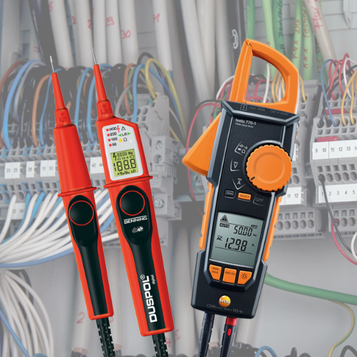
Testing electrical equipment is done using a range of specialized instruments to guarantee safety and correct functioning of the equipment. Such instruments include:
- Multimeters – These all-in-one devices conduct diagnosis for voltage, current, and resistance for the relevant circuits.
- Insulation Testers – Used to ascertain the effectiveness of wire insulation to restrict the flow of electricity.
- Clamp Meters – Measures current at greater levels without breaking the circuit.
- Voltage Testers – Used to indicate presence of voltage in a circuit or an electrical outlet; tools for confirming voltage level.
- Circuit Analyzers – Measures and analyzes the performance of a circuit, determining for common faults such as ground faults and improper wiring.
To ensure that electrical systems are functioning efficiently, strategically using these aids aids reduces the risk involved with testing.
Overview of Common Electrical Testing Tools
- Infrared Thermographic Cameras – These devices are extremely helpful in identifying hot spots in electrical panels, wiring or equipment that can lead to failures and even overloads. They are useful for capturing temperature variations and also enable preventative maintenance which further avoids any detrimental downtimes.
- Power Quality Analyzers – Power quality analyzers serve as an imperative tool for measuring proactively with the voltage, current, and any harmonic distortion within the electrical systems. These analyzers also make sure that all compliance requirements are met while, at the same time, help in finding any equipment performance disruptions or inefficiencies.
- Clamp Meters with Wireless Connectivity – New models of clamp meters are equipped with wireless capabilities and transmit information in real time. This feature allows monitoring and analysis of electrical parameters from a distance, thus enhancing safety in high voltage areas.
- Insulation Resistance Testers – These tools identify breakdowns at potential electrical failure or safety hazard points in equipment, cables, and motors.
The use of such complex devices equips specialists to accurately and effectively diagnose and rectify faults in electrical systems and troubleshoot these systems, thus ensuring system reliability and operational risk mitigation.
Comparison of Multimeters and Insulation Testers
|
Parameter |
Multimeters |
Insulation Testers |
|---|---|---|
|
Primary Purpose |
General electrical measurements |
Insulation integrity testing |
|
Measurement Capability |
Voltage, current, resistance |
High resistance (MΩ/GΩ scale) |
|
Typical Applications |
Circuit testing, troubleshooting |
Insulation testing in cables, motors |
|
Voltage Range |
Low to moderate (up to ~1,000V) |
High voltage (up to ~10kV) |
|
Resistance Range |
Low to medium resistance levels |
High resistance for insulation evaluation |
|
Safety Testing |
Not suitable for insulation testing |
Specifically for insulation safety and breakdown check |
|
Portability |
Compact and handheld |
Often bulkier, though portable models exist |
|
Display Readouts |
Digital or analog, multi-parameter |
Digital, focused on insulation measurement |
|
Cost |
Affordable, widely available |
Higher cost due to specialized testing features |
|
Advanced Features |
Frequency, capacitance, temperature options |
Polarization index, dielectric absorption ratio |
|
Industry Use |
General electronics, electrical repairs |
Industrial, power utilities, critical installations |
|
Precision at High Range |
Limited for very high resistance |
Superior accuracy for high resistance testing |
|
Power Source |
Battery-powered |
Battery or mains-powered |
How to Verify the Integrity of Electrical Systems?

To check an electrical system’s boundaries and parameters, do the following steps:
- Visual Inspection
Inspect all components and their electrical wiring visually, checking for signs of wear, corrosion, loose connections, or other damage in the physical components.
- Conduct Insulation Resistance Testing
Measure insulation resistance using an insulation resistance tester between the conductors and the earth. Check that the values obtained do not fall below the manufacturer’s recommendations or regulatory standards.
- Check Continuity
Ensure all electrical circuits are complete through continuity testing as this determines open circuits, bad connections, or damaged wires.
- Perform Load Testing
Evaluate the stability of the system while under expected load to determine performance, ensuring no parts are overheating.
- Grounding System Verification
Evaluate the system’s ground and confirm safe and low-resistance paths for fault currents verify the grounding system’s provided.
- Record and Analyze Results
Perform all tests and document the results, then analyze them against the set values and industry benchmarks for better diagnostics.
Following these steps helps improve electrical systems by identifying risks and automated detection. Be to follow safety practices such as using protective gear while reading technical documents.
Techniques for Assessing Electrical System Integrity
- Insulation Resistance Testing
This method uses direct current (DC) voltage on insulation to measure resistance. High resistance value means the insulation is intact while low values indicate various levels of wear, degradation, or failure points. Regular testing is critical for monitoring wear in high voltage systems.
- Thermographic Inspection
Loose electrical connections, overloaded circuits, failing components, and a number of other issues can all manifest in the form of heat. Thermographic inspections utilizes imaging technology to viably detect these thermal irregularities. As such, this non-invasive method is excellent for preventive maintenance because it detects problems before they escalate into critical failures.
- Power Quality Analysis
Monitoring parameters such as the voltage, current, and frequency also helps analyze stability within the electrical system thermographic. To capture the data reflection of voltage, sagging, harmonic distortion, and transient, power quality meters or analyzers are used. These factors affect reliability as well as system efficiency.
- Circuit Continuity Testing
This test effectively ensures that current will remain uninterrupted throughout a circuit. For this active and passive positron emission tomography and austin source numbering method, verifying the integrity of connections at various nodes is performed, critical for diagnosing open circuits or faulty wiring.
Importance of Electrical Testing in Preventing Equipment Failures
Regular testing of electrical systems helps to manage the hazards associated with system failures and enhances operational efficiency and safety. Statistics suggest a sizable fraction of equipment breakdowns go unrecognized due to certain electrical errors such as insulation failure, loose fittings, or shorting. Organizations are better served by conducting routine assessments such as infrared thermography, insulation resistance tests, and circuit analysis, as these enable detection of preemptive issues that if resolved, avert costly downtimes or dangerous failures. Moreover, modern diagnostic tools with advanced sensors can monitor in real time, yielding exact and critical measurements on parts and systems and outlining weak areas. Adopting these methods slows down the rate of failure for equipment while enhancing compliance with safety regulations and precautionary measures which justifies the need for routine electrical assessments in preliminary industrial and commercial frameworks.
What Are the Best Practices for Electrical Testing?

1. Follow Compliance: Observe specific compliance frameworks such as the National Electrical Code (NEC) and Institute of Electrical and Electronics Engineers (IEEE) which provide baseline requirements for uniformity, protection and compliance.
2. Schedule Routine Assessments: Define a calendar schedule for testing to catch stubborn issues long before they become major problems, covering visual inspection, thermal imagining, and electric performance measuring.
3. Traceable Standards: Maintain and document all measuring and test equipment and ensure observance of all documented procedures to guarantee accurate and dependable outputs.
4. Enforce Safety Protocols: Apply appropriate safety measures like donning insulated gloves and confirming no voltage prior to testing, as well as exercising lockout and tagout methods.
5. Complete Documentation of Findings: Document every test meticulously, specifying the date, equipment examined, problems noticed, and actions resolved, along with all supporting evidence. Strong records assist with regulatory compliance and play a key role in aids future servicing.
Adhering to these highlighted procedures enables businesses to improve operational safety, reduce downtimes, and achieve long-term equipment reliability.
Safety Measures During Electrical Testing Procedures
Following safety measures during the electrical testing procedures protects personnel from possible injuries, prevents damage to equipment, and avoids compliance issues. Identified below are critical safety procedures which must be adhered to.
- Personal Protective Equipment (PPE): Approved PPE for minimizing risk includes face shields, insulated gloves, dielectric footwear, and arc-rated clothing. PPE should comply with industry standards such as ASTM F1506 or NFPA 70E.
- Pre-Test Inspection: Testing tools and relevant equipment should be visually inspected prior to use. Signs of wear such as exposed circuitry or frayed insulation pose considerable risks.
- Verify Proper Isolation: Be sure to de-energize the system and abide by lockout/tagout (LOTO) requirements. Tests should only be carried out after ensuring the use of voltage detection devices to guarantee zero energy.
- Environmental Assessment: Assess conductive materials, temperatures, moisture levels, or spaces which may be confined as these create electrical risks and hazards.
By following the outlined safety measures, there would be compliance with OSHA 29 CFR 1910.331-335, NFPA 70E and workplace safety regulations while improving efficiency during electrical testing operations.
Documenting Test Results for Future Reference
Proper documentation of electrical testing is important in maintaining traceability and compliance with regulations. Following proper regulatory practices is crucial for precision and documentation order.
- Standardized Data Recording: Make use of software systems which capture test values in a uniform manner as designed in the provided templates. Every piece of equipment should have its own template, which contains its identification, conditions under which each test is conducted, methodologies employed, voltage, current, and resistance levels.
- Timestamping and Version Control: Every test entry should have a timestamp set against it so that chronological tracking becomes effortless. In cases where multiple tests are conducted on the same apparatus, unique timestamps should be created for every test, with the appropriate version control in place to distinguish updates clearly.
- Visual Documentation: Supplementary materials can include diagrams to photograph equipment setups or even annotated screenshots from digital testing devices. These diagrams and photographs greatly assist contextual meaning and serve to eliminate gaps in knowledge when the data is intended to be analyzed later on.
- Metadata and Contextual Notes: Append environmental conditions such as temperature and humidity, along with deviations from standard procedures as metadata to test records. Outline the objective alongside detailing any abnormalities in the notes to be added.
With these strategies, organizations can optimize their data use, enable cross-team collaboration, reduce the risk of incomplete or missing test information, and more.
Reference Sources
-
AI in Electrical Equipment
This paper discusses the role of AI in smart manufacturing, predictive maintenance, and grid optimization over the past five years. Read more -
Global Testing Equipment and Services Market (2020 to 2025)
A market report analyzing trends, growth, and forecasts in the testing equipment and services sector. Read more -
Electrical Test Equipment – Market Share Analysis
This report provides insights into market trends, industry statistics, and growth forecasts for electrical test equipment. Read more -
Electrical Testing Innovations
A LinkedIn article discussing the latest innovations in electrical testing, including smart devices and wireless testing. Read more -
An Overview of Testing Methods for Electronic Components
This blog post explains various testing methods used in the electronics industry. Read more
Frequently Asked Questions (FAQs)
Q: What is a multimeter and how is it used in electrical testing?
A: A multimeter is a versatile instrument used to measure various types of electrical parameters such as voltage, current, and resistance. It is a crucial part of a comprehensive guide to electrical testing equipment, enabling technicians to assess the functionality of electrical systems and components effectively.
Q: What is the purpose of a continuity test in electrical work?
A: A continuity test is used to determine if there is a complete path for current to flow in an electrical circuit. This type of test helps ensure the safety of electrical systems by identifying breaks or faults in wiring and connections.
Q: How do I choose the right test equipment for voltage testing?
A: Selecting the right test equipment for voltage testing is vital for the reliability and safety of electrical installations. Consider the voltage range, accuracy, and type of test you need to perform. A comprehensive guide to electrical testing equipment can help you make informed decisions.
Q: What are insulation resistance testers and why are they important?
A: Insulation resistance testers are devices used to measure the insulation resistance of electrical systems and components. They are crucial for ensuring the safety and effective operation of electrical systems, as they help prevent electrical failures and hazards.
Q: Can modern electrical testing equipment automate the testing process?
A: Yes, modern electrical testing equipment often includes features for automated testing, which increases efficiency and accuracy. Automated systems can streamline the testing process, providing quick results while ensuring compliance with safety standards.
Q: What types of tests are included in a complete guide to electrical testing?
A: A complete guide to electrical testing typically includes various types of tests such as voltage testing, continuity tests, insulation resistance tests, and functional tests. Each type of test plays a unique role in assessing the reliability and safety of electrical systems.
Q: How often should electrical testing be performed on high-voltage equipment?
A: Electrical testing on high-voltage equipment should be performed regularly to ensure the safety and reliability of electrical systems. The frequency of testing can depend on the usage, environmental conditions, and specific regulations governing electrical work.
Q: What is the significance of testing the functionality of electrical devices used in installations?
A: Testing the functionality of electrical devices used in installations is essential for identifying potential issues that could lead to failure. This process is part of ensuring the overall safety and efficiency of electrical systems and can prevent costly repairs and downtime.
Q: How does electrical testing contribute to the overall safety of electrical systems?
A: Electrical testing is critical in evaluating the reliability and safety of electrical installations. By conducting various types of electrical testing, technicians can identify faults, ensure compliance with safety standards, and maintain the effective operation of electrical systems.